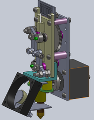
A Nema14 compact dual drive geared extruder
Release status: working
| Description | A dual drive geared extruder made with a Nema14 motor.
|
| License | |
| Author | |
| Contributors | |
| Based-on | |
| Categories | |
| CAD Models | |
| External Link |
Introduction
In an earlier post [1] I described a dual drive geared extruder made entirely from scratch and explained why this design could be better than others projects of geared extruders. With ABS and hot end set to 220C and a 0.4 mm nozzle the extruder yielded a flow rate of 25 mm3/s, a good result. But the overall assembly was bulky (but no problem if its used as a Bowden extruder). In this post I describe a more compact version of a Dual Drive Geared Extruder, made with a Nema14 motor. The motor/drives transmission rate was 69:15. The motor used (Applied Motion model 5014-819) was saved from an old table scanner. Each motor coil have a resistance of 3.8 Ohms and a recommended motor current of 0.5 A. A A4988 driver from the RAMPS1.4 shield can easily run such a motor, but as the motor size and current were small, I wondered if I could obtain a reasonable flow rate. To my surprise, I could obtain a flow rate of almost 22 mm3/s, similar to the former development shown in [2]. At the end of this post is a video that shows a test of the extruder. It was possible to obtain 1.75mm filament feed rates of almost 10 mm/s (or flow rate of almost 25 mm3/s) without slipping or motor stalling. The A4988 motor driver was set to use 4 microsteps. The Marlin Firmware was configured to use 162 Steps/mm.
Overview
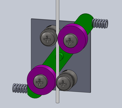
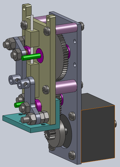
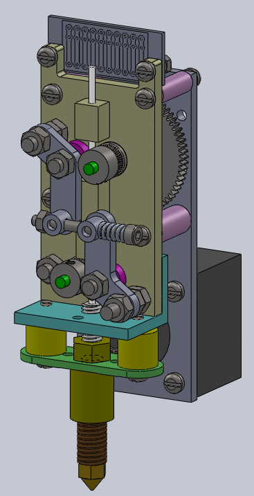
The stepper motor and gears used in this project were saved form old laser printers and table scanners. The other parts were made with aluminium scraps using a lathe and a milling machine or 3D printed in PLA. I had in my scrap gears box three modulo 0.5 gears: a smaller one with 15 teeth and two larger, with 69 teeth each. The shaft of a Nema14 stepper motor is attached to the 15 teeth gear. This gear is coupled to a 69 teeth gear connected to the first hobbed drive. The rotation is reversed by another 69 teeth gear that is connected to the second hobbed driver. Therefore, the motor/drivers transmission speed ratio was 4.6:1. In this design the filament is pressed in opposite sides by bearings supported by a lever, as shown in the figure bellow. The MK8 hobbed gears were made from scratch as well [3].
The main advantages of this design are:
The gears distance does not vary. They are tightly coupled to have minimum backlash.
The filament is griped in two opposite sides.
Radial force on motor shaft is minimized.
The mounting sequence of the extruder is shown in sections ahead. All CAD files, images and STEP files can be downloaded from: [4].
Mounting sequence
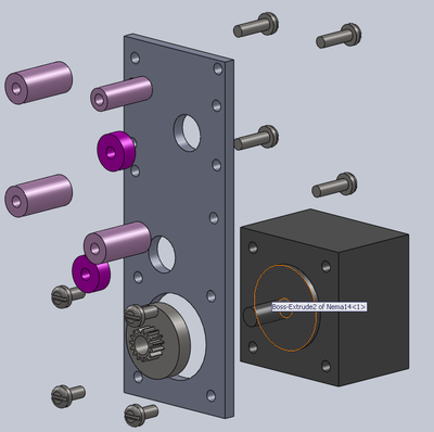
The rear plate of the extruder was machined in Aluminium. The first steps consist on attaching the Nema 14 motor and inserting the bearings for the gears' axis. Attaching the motor to an aluminium plate is useful to act as a heat sink for the motor. Some attempts to 3d print the back plate in PLA did not worked: trying to overdrive the motor's current to increase the flow rate heated the motor to a temperature high enough to melt the PLA backplate.
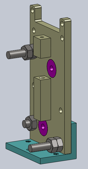
The next two figures show the mounting of the PLA front plate. The bearings for the gears' axis are inserted and should match tightly in their holes. At the bottom is attached an aluminium bracket to support the hot end.
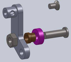
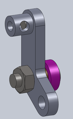
The four figures below show the mounting of the two pressing arms to the front panel. The pressing arms are made in aluminium.
Next step is to attach the front and rear plates together, as shown in the two figures below.
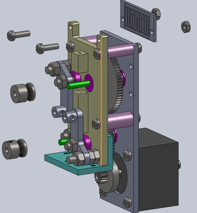
Now its time to insert the two hobbed MK8 drivers and the PCB board to solder the motor, heater and thermistor wires. The cold end of the extruder is almost ready.
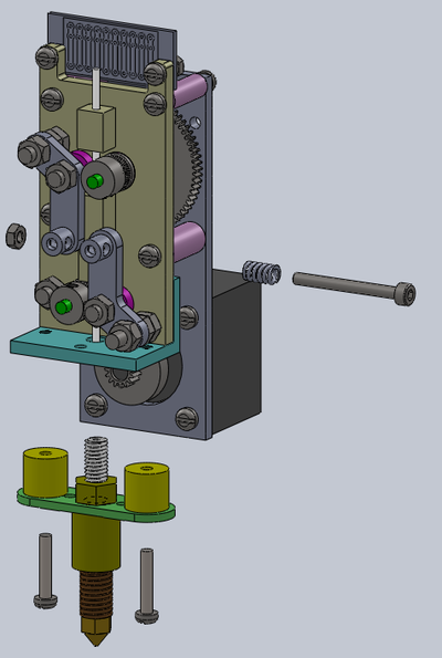
The pressing screw and spring are attached to finish the cold end part of the extruder. The Hot End is mounted is the aluminium bracket, as shown in figures 14 and 15:
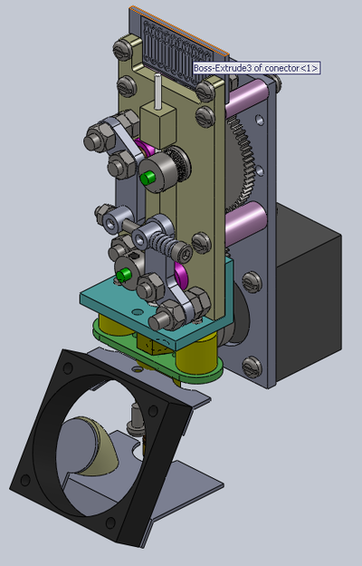
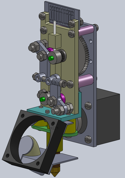
To finish, the cooler is fixed in the aluminium bracket as shown in figures 16 and 17.
Conclusions
This ends the description of a more compact version of a dual driver geared extruder. With ABS and hot end set to 220C and a 0.4 mm nozzle the new extruder yielded a flow rate of 22 mm3/s, a good result if you consider that I used a small Nema14 stepper motor model. When I tried to increase flow rate beyond 22 mm3/s the motor stalled, but there were no slipping or grinding of filament. I suppose that with a more powerful motor I could obtain higher flow rates. With such a powerful extruder I could print 0.2 mm layers with feed rate around 220 mm/s !
The video below shows the test made with the extruder. In this test I extruded 50 mm of a 1.75 mm filament varying the feed rate from 1 mm/s to 10 mm/s. The extrusion length did not decreased as the feed rate increased, a common problem to many extruders. There was no slipping at all. The upper limit was reached when I used a feed rate of 10 mm/s, At this feed rate the motor stalled, and you can hear the characteristic "click" in the video, at 3:16:00.
