Adding more extruders
Release status: working
| Description | Upgrading your printer
|
| License | Public Domain
|
| Author | |
| Contributors | Mykal451
|
| Based-on | |
| Categories | |
| CAD Models | |
| External Link |
This page is made as a help to those who are planning on upgrading their existing printer with one or more extruder motors.
It was originally made with the Diamond Hotend in mind and therefore primarily focuses on connecting additional extruder motors to existing boards.
Contents
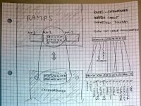
RAMPS using Stepper Expander
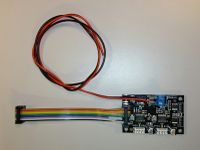
See the Stepper Expander page for further information on this particular board
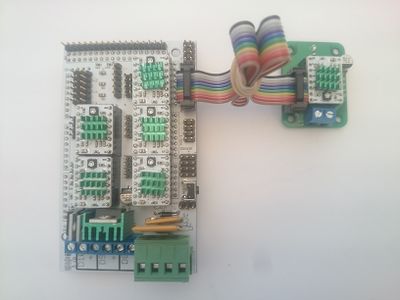
Adding a third extruder motor:
- Mount the Stepper Expander close to the RAMPS board.
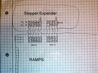
- Attach a 2x5p IDC cable from the RAMPS' AUX-2 expansion pins to the Stepper Expander pins, observe orientation.
- Attach wires to the Stepper Expander's screw terminals Vmot is positive and Gnd is negative.
- Connect the third motor onto the Stepper Expander.
- Make the firmware changes listed below
Firmware Changes
In Pins.h:
#define E2_STEP_PIN        64
#define E2_DIR_PIN         59
#define E2_ENABLE_PIN      44
Where to get it:
RAMPS using RAMPSXB
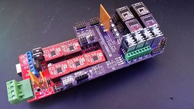
RAMPSXB is an expansion board for the RAMPS that adds 4 more stepper drivers, 4 more thermistor inputs, and 4 more heaters, among other goodies. It's designed to socket into the open headers of the RAMPS and add additional functionality.
Begin by attaching A4988 or DRV8825 drivers into their carriages. After that, socket the RAMPSXB to the RAMPS
And that's it, the RAMPS is now ready for 4 more extruders!
Firmware Changes
For more information about features and firmware changes, see the full wiki page here: RAMPSXB
Where to get it:
RAMPS using ExtrudrBoard
Adding one or two extruder motors using ExtrudrBoard
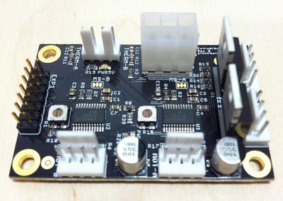
ExtrudrBoard is a daughter board comprised of two Allegro 4982 or 4988 stepper drivers along with two thermistor inputs as well as two heater outputs. It was designed to work as an expansion board for PrintrBoard by the people over at PrintrBot, but can be used for nearly any other board as well.
If your existing electronics board has only one extruder and you want the capability of up to two additional extruders, you will need:
- Three or six available general purpose I/O (GPIO) pins (using 5 volt logic). On your main board there is probably an unused row of pin headers called EXP1, EXP2 or EXP3. See the documentation for your board to find the correct pin numbers/references to use in the firmware changes below.
- +5V and GND wiring (which is usually available from the EXP1, 2 or 3 headers too)
- 12 volt power (ATX P6 type plug) from your power supply. (the board can also run on 24 volt if that is what your machine already uses)
Connect the following pins from the ExtrudrBoard:
- GND
- +5V
plus
- A-STEP
- A-DIR
- A-ENABLE
and/or
- B-STEP
- B-DIR
- B-ENABLE
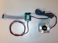
The picture below shows the pinout on the ExtrudrBoard:
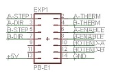
If you are using this in conjunction with the Diamond Hotend, those are all the connections you need to your mainboard since it only needs one thermistor and one heater (which should already be connected directly to the terminals on your existing mainboard).
Firmware Changes
In Marlin's Pins.h you need to #define the correct pin number to:
- E1_STEP_PIN
- E1_DIR_PIN
- E1_ENABLE_PIN
and/or
- E2_STEP_PIN
- E2_DIR_PIN
- E2_ENABLE_PIN
If you have three separate hotends (e.g. not using the Diamond Hotend) you also need to locate four additional GPIO pins and define them in firmware:
- HEATER_1_PIN
- TEMP_1_PIN
and/or
- HEATER_2_PIN
- TEMP_2_PIN
Beware: the TEMP_ pins must be Analog ADC pins. For reference please see the documentation for your motherboard MCU.
Lots of technical knowledge on the ExtrudrBoard as well as images and diagrams can be found at PrintrBot forum and the source files at GitHub
Where to get it:
RAMPS using CNC Shield
This outlines the hardware connections required to add an extruder to your existing RAMPS board for cheap.
Parts needed (Can All Be Bought from China for Under $10 Shipped to the US):
- 1 x CNC Shield v3. Can Be had for $3.70 from China
- 4 x 10cm Female to Female Jumper Wires
- 1 x 20cm Female to Female Jumper Wires (You can use all 5 20cm if you want.)
- 1 x Stepper Motor Driver DRV8825 Or A4988 (China Clones Can be Had for Under $1.70 for DRV8825
- 5 x Standard Header Jumpers
- 2 x Short Scrap Stranded Wire 18 AWG or Larger.
- 2 x M3 Screws 8-16mm Length
- 4 x M3 Nuts
- 1x Printed RAMPS Bracket [1] DO NOT USE THIS. Causes Shorts When you use the nut as a spacer.
Steps:
- Start by printing the bracket
- Attach the bracket to the CNC board with the M3 Screws.
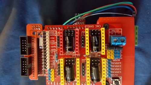
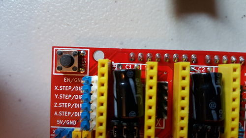
- Install the 5 Jumpers as shown here.
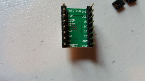
- Find The Enable pin on your stepper Driver
- Make Sure the Enable Pin on your driver lines up with the enable pin on the CNC Shield then install it into the shield on the A Axis (Typically the Red Colored Headers)
- Examine the pin locations here and make the following connections: [[2]]
* AUX-1
* 5v to 5v on CNC Board
* GND to GND on CNC Board
* D1 to A.Step on CNC Board <-- Not advisable, conflicts with serial communications TX0, Use D57
* D0 to A.Step Direction on CNC Board <-- Not advisable, conflicts with serial communications RX0, Use D58
* AUX-2
* D66 to Enable on CNC Board Using 20cm Wire
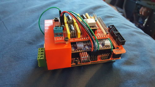
- Final Connections Should look something like this:
- Hook Up to 12v or 24v supply on the CNC Board. (It does not need to be the same supply as the rest of the RAMPS Board ex. if you do not have enough current from 1 power supply.)
This method can be used to add up to 4 extra motors while still leaving 4 IO pins, fan extender, and LCD functional. There is no need to go buy an expensive board meant for a kraken because we only use 1 heater.
This method can also be used for other boards like (Melzi, Ultimaker, Printrboard, etc.)
Firmware Changes
Note: This will only work if being done for a RAMPS 1.3 or 1.4 Board. In configuration.h change the lines to the following:
#define EXTRUDERS 3
#define TEMP_SENSOR_0 6
#define TEMP_SENSOR_1 6
#define TEMP_SENSOR_2 6
Ensure it is setup so the power outputs are for only 1 extruder. i.e, one of the following:
#define MOTHERBOARD BOARD_RAMPS_13_EFB
#define MOTHERBOARD 33
#define MOTHERBOARD BOARD_RAMPS_13_EFF
#define MOTHERBOARD 35
The top 2 are equivalent and have the power outputs for an extruder, fan and bed (EFB), the bottom 2 are equivalent and have power outputs for an extruder and 2 fans (EFF).
And in pins.h: You may need to add:
#define E2_MS1_PIN -1
#define E2_MS2_PIN -1
In the RAMPS section (under where it has "if IS_RAMPS", after the else for if MB(3DRAG), if it has #define SDPOWER right after it is the wrong one) you need to add:
    #define E2_STEP_PIN        0  //<- Not advisable, D0 is RX0 will conflict with serial communications, use D58
    #define E2_DIR_PIN         1  //<- Not advisable, D1 is TX0 will conflict with serial communications, use D57
    #define E2_ENABLE_PIN      66
If you chose EFF, then change:
  #if MB(RAMPS_13_EFB) || MB(AZTEEG_X3)
    #define HEATER_1_PIN       -1
  #else
    #define HEATER_1_PIN       9    // EXTRUDER 2 (FAN On Sprinter)
  #endif
To
  #if MB(RAMPS_13_EFB) || MB(AZTEEG_X3)
    #define HEATER_1_PIN       -1
  #else
    #define HEATER_1_PIN       -1    // EXTRUDER 2 (FAN On Sprinter)
  #endif
And change the following (near line 700):
#define TEMP_1_PIN 13
And shortly below, after the else:
#define TEMP_2_PIN 13
