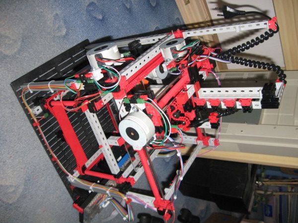
FTIStrap
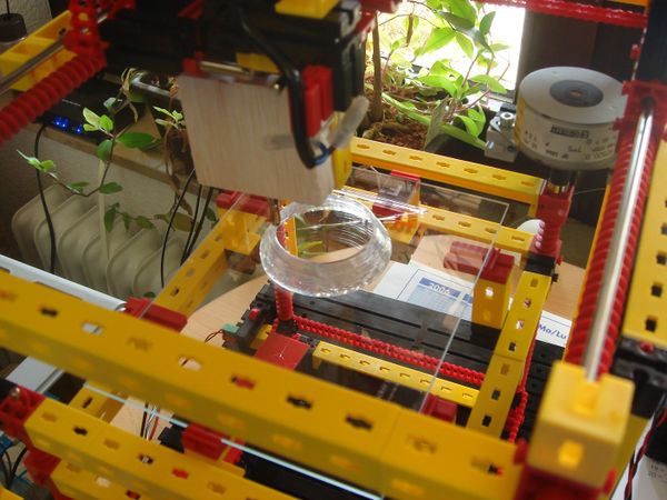
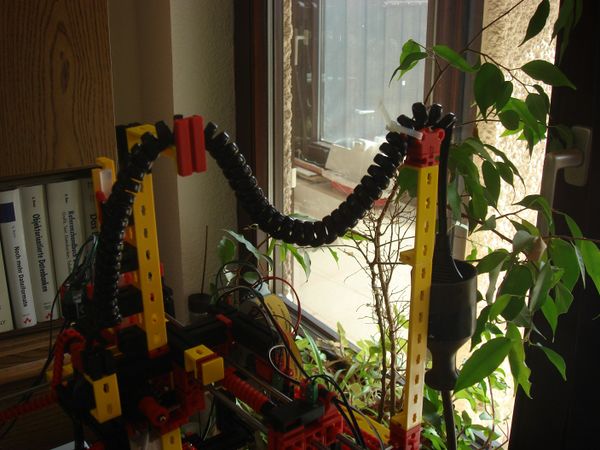
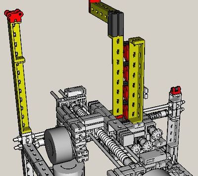
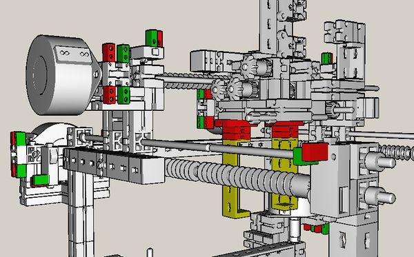
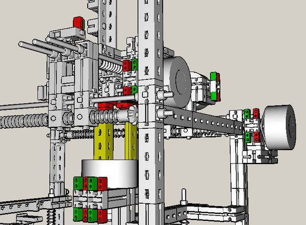
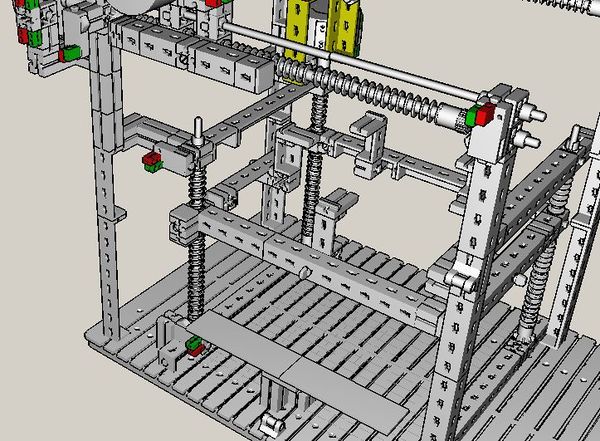
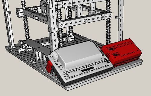
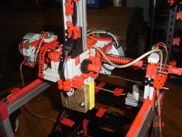
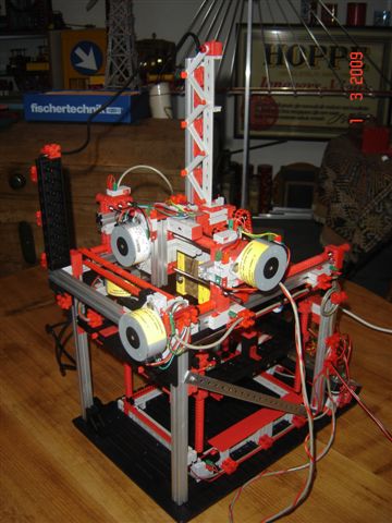
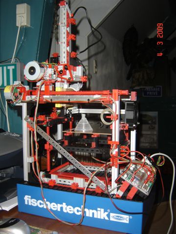
This page describes the "FTIStrap", a RepStrap [1,2] which is almost completely built from fischertechnik [3] parts. Constructing an FTIStrap neither needs any special expertise nor any special tools and can usually be completed within a single working day. All parts can either be ordered online or found in many stores in your neighbourhood. After printing the parts for a RepRap the FTIStrap may even be disassembled again and its parts used for other projects.
(It's done: the assembly instructions are complete now and a very first version of the controller software is available for download - just proceed to Software Downloads below)
Another note: it is done - the "didacta 2009" fair in Hannover is over! More than 400 visitors came to my booth in order to see the FTIStrap in action and learn about the underlying technology. And quite a few of them announced their intention to build a copy of this 3D printer!
The author knows of two first copies of the FTIStrap which have been built so far (in Germany and the Netherlands). Proceed to chapter Copies of the FTIStrap to see photographs of these models! Congratulations!
By the way: meanwhile, the FTIStrap has been elected as the "fischertechnik model of the period January to March 2009" (see http://www.fischertechnik.de, under "Fanclub" -> "Gallery") - Thanks to all who voted for me!
Contents
- 1 Introduction
- 2 Part List
- 3 Extruder Construction
- 4 FTIStrap Assembly
- 5 Cabling
- 6 Driver Software
- 7 Initial Startup of the FTIStrap
- 8 Operation Manual
- 9 Tips and Tricks
- 10 Material Recycling
- 11 Software Downloads
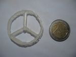
- 12 Example Objects
- 13 Modifications and Extensions
- 14 Events
- 15 Copies of the FTIStrap
- 16 Future Plans
- 17 Configuration File Format
- 18 References
Introduction
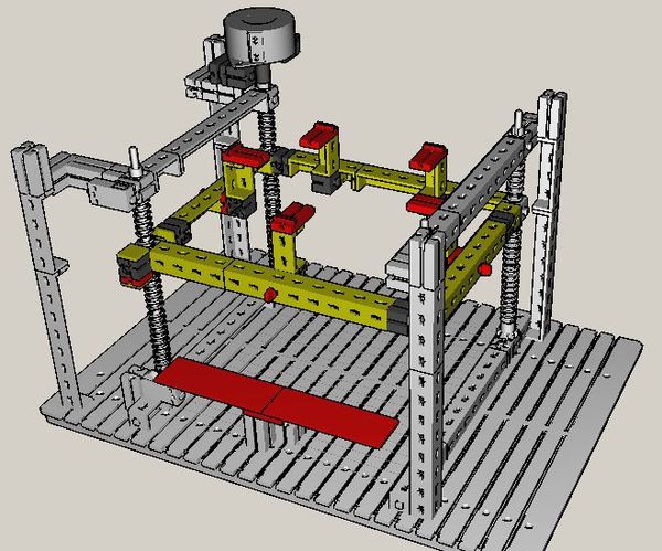
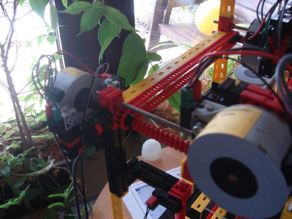
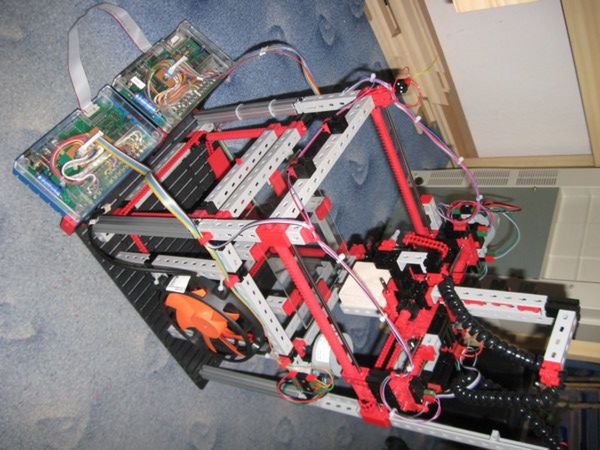
The FTIStrap is a "RepStrap" which almost completely consists of fischertechnik parts. Stepper motors are used as actuators, the interior of a hot-melt gun forms the extruder and a (removable) glass plate acts as the base to print on. A fischertechnik "Robo Interface" together with an extension module (both running in "online mode") control the steppers and scan the end stops - they can be connected to an IBM-compatible PC running Windows or Linux or an Apple Macintosh running MacOS X. The FTIStrap is completely "host-controlled" - a small application running on the host can be used to either manually operate the machine or load and interpret a file containing the "G codes" for a RepStrap.
The FTIStrap's main "advantages" are
- it almost completely consists of fischertechnik parts - including the four steppers and any electronics - and everything can be ordered online [4]
- the few remaining parts (hot-melt gun, balsa wood, sand paper, glue, fan, glass plate) can also either be bought online or found in various shops in your neighbourhood
- no special tools are required to build the FTIStrap - although a hacksaw is recommended to cut the balsa wood which covers the hot-melt gun
- no soldering is required - all the electronics you need is already available from fischertechnik
- when all parts are available, the whole FTIStrap can be easily assembled within a single working day
- as soon as you no longer need the FTIStrap (because you used it to build your own RepRap), it can be disassembled again and its parts used for other projects
The current printing characteristics are
- position accuracy: approx. 0.1 mm in all directions (i.e., approx 256 lpi)
- material thickness in xy direction (i.e. line width): approx 1.0 mm
- material layer thickness (z direction): approx 0.5 mm
The hot-melt gun which is currently used needs cylindrical hot-glue sticks with a diameter of 7mm. The gun melts them at a temperature of approx. 230° celsius which is hold by a thermistor within the gun. The rigidity of the printed objects depends on the thickness of their walls (in relation to their size, of course): one of the first printed test objects, which accidentially got thicker than foreseen, turned out to be really rigid.
Warning! Use at your own Risk!
If you plan to build your own copy of the FTIStrap, play around with it and/or show it to other people, please read the following paragraph carefully:
- the hot-melt gun operates at 220V and - although the cabling seems to be professionally insulated (see the pictures below) - handling close to the cables might be dangerous!
- the hot-melt gun operates at approx. 230° Celsius - do not touch the nozzle, it's hot!
- should you have damaged the insulation between the heating element of the hot-melt gun and its metallic parts, the nozzle is not only hot but also connected to 220V power!
Thus: never let the FTIStrap operate unattended - especially if visitors are near. Keep it away from young children! Before presenting your machine to others, tell your visitors that they must not touch the machine - under no circumstances!
The author must never be held liable for any damages or injuries caused by your own copy of the FTIStrap - use it at your own risk!
Part List
Originally, the list of fischertechnik parts has been automatically generated by the "fischertechnik designer" [5] which was used to model the FTIStrap and document its building phases. It has then been extended by the author (e.g., to include the chain elements) and modified (to be able to order "bags" with many parts rather than having to order every kind of item individually).
You will need the following items (the english part names are the author's (probably naive) translations from their german counterparts - if you have the "official" names, do not hesitate to fill them in here. Nevertheless, the part numbers should help you identifying the proper items)
- 1 x 35602 base plate 390x270 (Grundplatte 390x270)
- 16 x 36294 angle bracket 120,yellow (Winkelträger 120, gelb)
- 14 x 36297 angle bracket 60, yellow (Winkelträger 60, gelb)
- 19 x 36299 angle bracket 30, yellow (Winkelträger 30, gelb)
- 6 x 35053 angle bracket 15, yellow (Winkelträger 15, gelb)
- 5 x 35076 static brick (Statikstein, gelb)
- 9 x 32850 bar brick 15x15 (Riegelstein 15x15)
- 5 x 36323 s bar 4 red (S-Riegel 4 rot)
- 36 x 32064 brick 15 with hole (Baustein 15 mit Bohrung)
- 12 x 32879 brick 30, black (Baustein 30 schwarz)
- 30 x 32881 brick 15, black (Baustein 15 schwarz)
- 10 x 32882 brick 15 with two plugs (Baustein 15 mit zwei Zapfen)
- 4 x 31011 angle brick 30 degrees (Winkelstein 30 Grad)
- 3 x 37238 brick 5 with two plugs (Baustein 5 mit 2 Zapfen)
- 26 x 37237 brick 5 (Baustein 5)
- 15 x 35049 brick 15x30x5 with slot and plug (Baustein 15x30x5 mit Nut und Zapfen)
- 14 x 37468 brick 7.5 (Baustein 7.5)
- 26 x 31982 flute pin (Federnocken)
- 1 x 31061 connector 30 (Verbindungsstück 30)
- 8 x 31060 connector 15 (Verbindungsstück 15)
- 19 x 38236 plate 15x15, yellow (Bauplatte 15x15, gelb)
- 2 x 38251 plate 30x90, red (Bauplatte 30x90, rot)
- 2 x 38428 plate 15x30x5 with three slots (Bauplatte 15x30x5 mit 3 Nuten)
- 1 x 31034 metal rod 30 (Metallachse 30)
- 2 x 37384 metal rod 80 (Metallachse 80)
- 2 x 31031 metal rod 110 (Metallachse 110)
- 4 x 35697 metal rod 200 (Metallachse 200)
- 33 x 37679 clamping bush 5 (Klemmbuchse 5)
- 9 x 35112 bevel Z10, M1.5 (Ritzel Z10, M1.5)
- 8 x 31915 screw nut (Zangenmutter)
- 6 x 35113 tongs (Spannzange)
- 11 x 37858 clampable worm m=1.5 (Klemmbare Schnecke m=1.5)
- 32 x 37926 worm element m=1.5 (Schneckenteil m=1.5)
- 9 x 37925 worm nut m=1.5 (Schneckenmutter m=1.5)
- 2 x 35695 gear Z15 (Zahnrad Z15)
- 2 x 32649 bag of chain links (Rastkettenglied Beutel)
- 1 x 37636 roller bearing (Rollenlager)
- 5 x 32085 roller bracket (Rollenbock)
- 4 x 31436 hinge claw (Gelenkwürfel-Klaue)
- 4 x 36819 bearing sleeve (Lagerhülse)
- 6 x 37783 mini switch (Mini-Taster)
- 30 x 31336 contact pin, green (Flachstecker, grün)
- 30 x 31337 contact pin, red (Flachstecker, rot)
- 4 x 32311 Stepper Motors
- 4 x 75045 bag with parts for a stepper motor (Teilebeutel für Schrittmotor)
- 1 x 93293 Robo Interface
- 1 x 93294 Robo IO-Extension
- 1 x 79015 stepper motor hints (Hinweise zum Schrittmotor) just for your information, not really necessary
It seems as if some of the axes the author used for constructing the FTIstrap are no longer available - you will have to get them from other sources. The following axes are needed:
- 4 x axes 300mm (4mm diameter)
- 3 x axes 250mm (4mm diameter)
It should not be too difficult to cut metal rods of an appropriate diameter to the proper length. Steel rods would be the best choice, but brass might be easier to cut.
Besides the fischertechnik parts, you will also need
- a Proxxon hot-melt gun (Proxxon no. 28192, or a similar one if you don't mind modifying the extruder casing and its feeder)
- a strip of balsa wood (10mm thick)
- some heat-resistant glue (the author used "Uhu hart" for that purpose)
- a little bit of (rough) sand paper (to cover the cylindrical drives of the hot-glue feeder)
- a glass plate (17.2x12.5 cm*cm, taken from a "frame-less picture frame" which usually costs less than 1€)
- a cheap fan (12x12 cm*cm, 12V)
- some cable straps
- some silicon oil (to reduce friction along the plastic thread rods)
- if need be: a USB-to-Serial converter and/or a serial cable (do not forget that!)
- if need be: a 9V power adapter for the fischertechnik interfaces (if you do not want to buy the fischertechnik PowerBlock)
- if need be: a 12V power adapter for the fan
and, of course, you will need
- hot glue sticks (e.g., Proxxon no. 28194, or similar - depending on your actual hot-melt gun)
The tools you should have:
- a small screw driver (for the fischertechnik steppers - you may order them together with the other parts)
- a sharp knife (to carve the balsa wood into shape)
- a frame saw (to cut the balsa wood - if need be, you may use the knife for that purpose, but a saw usually gives better results)
Extruder Construction
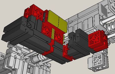
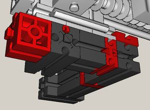
The extruder consists of nothing but (the interior of) a conventional hot-melt gun which was enclosed by layers of balsa wood and fixed within two fischertechnik parts (part no. 36297 or similar)
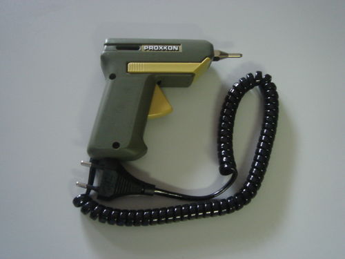
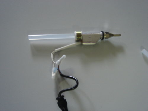
This is the Proxxon hot-melt gun (Proxxon no. 28192) which was actually used - if you prefer another one, you may have to modify the balsa wood casing (and probably the feeder as well).
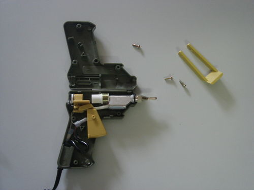
If you open the casing, you will see its inner parts:
Just take the heater element and remove everything else. Important: do NOT cut-off the silicon guide for the hot-glue sticks (as the author did on this picture) it is really important for the proper functioning of the gun! The author's first gun turned out to be completely useless and he had to buy a second one to proceed! The feeder is now by far strong enough to shift the sticks through the guide into the heater element.
The following picture shows all the parts you need to build the balsa wood cabinet for the hot-melt gun (well, almost all parts: the author forgot the heat-resistant glue that is needed to glue all parts together. You will see it later in the process).
The hacksaw is used to cut the balsa wood into parts which are then carved into their proper (irregular) shape using a pocket knife.
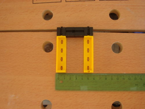
In order to get the proper size of the cabinet, you should assemble the following "bracket" and test, if your balsa wood parts fit into that bracket. Although the final mount will look different, this bracket will help while you cut the parts.
Take your balsa wood stripe (which must be 10mm strong) and cut a block of 52x56 mm^2 in size. Test if it fits.
Place the heating element on the balsa block and move it until both the inlet and the nozzle are horizontally centered. If you look at your heating element, you will recognize a thin ring just beneath the wide body: this ring should be placed as far away from the lower end of the cabinet as possible - during operation, this ring helps keeping the heating element firmly in its cabinet.
As soon as you have placed the heating element at its proper place you shoud press the ring into the balsa wood. This will produce a small cavity which may then be carved a little bit deeper with a pocket knife.
You may now mark the area covered by the heating element. It may later help you when you will have to carve a cavity for the filament.
Cut another balsa block of the same size (52x56 mm^2) and place the heating element on it as before - but do not forget to turn it around first! Again, press the ring into the balsa wood and carve it a little bit deeper.
You may mark the area covered by the heating element again:
Fortunately, the heating element is also approx. 10 mm strong - only the filament and the abovementioned ring need more space. For that reason, it is quite easy to produce the inner parts of the cabinet: just cut (and carve) some more balsa wood parts into shape - the marked areas will help you finding the required size for these parts!
Check if the part fits to the heating element.
The second (inner) part has slightly more complicated shape - thus, it's a good idea to mark the areas first, which are going be removed, before actually doing so.
Carve the part into shape and check that it fits.
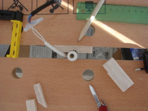
As mentioned above, the filament is larger than 10mm. For that reason, it is necessary to carve a small cavity into the outer balsa wood parts. The following picture illustrates how the result will look like (from above, look where the tip of the pencil points to):
The next picture shows the cavity from the side (the tip of the pencil points at it). Please, also note the small cavity for the ring that was mentioned before: in the picture it is the small area which has been marked with the pencil and therefore looks a bit darker than the rest of the marked area.
Always check that all parts fit.
Carve two more cavities (for the filament and the ring) into the other (outer) balsa block.
As soon as all parts fit nicely, you may start glueing the inner parts onto one of the outer ones. But beware: always keep the glue away from the heating element! The heating unit itself is never glued into its cabinet but will only be fixed by the balsa wood parts surrounding it!
Place the heating element within the inner parts - it will help you moving all parts into their proper positions.
Finally, glue the last balsa part onto the others and clamp the whole cabinet (with the heating unit inside!) together until the glue has hardened.
In a final step, you may sand and/or carve the edges of the cabinet in order to look nicely - but there is no real need to do so if the parts fit already. Afterwards, you should already glue the cabinet into the yellow parts of the bracket (part no. 36297) and clamp everything again, until the glue has hardened. Later, the fischertechnik parts will allow you to mount the extruder to the stick feeder and the cartesian bot (see phase twelve of the FTIStrap assembly).
FTIStrap Assembly
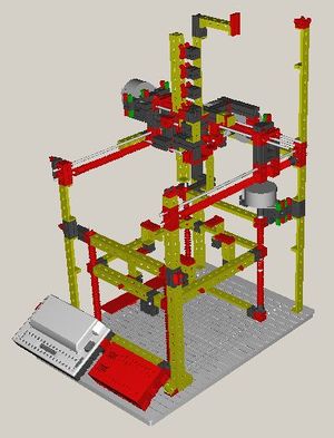
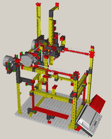
The author has used the "fischertechnik designer" [5] to create a model of the FTIStrap. This model was the basis for the following illustrations of the assembly process. These illustrations will hopefully help you constructing your own copy of the FTIStrap - if anything remains unclear, don't hesitate to ask the author for clarification.
The underlying model (FTIStrap.ftm) is also available for download: just right-click on the link and select "Save As.." in order to save the file on your local hard disk. You will need the latest version of the "fischertechnik designer" to open this file - you might need the full version as the demo version can only handle up to ten fischertechnik parts.
Phase 1
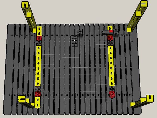
Let's start with the first parts of the outer frame and the base of the z axis lifter.
The part in the middle of the base plate (the one with the metal rod) will later be used to tighten the chain for the z axis lifter. The parts can be moved along the slot in the base plate, the second brick is just used to increase the friction and keep the brick with the rod in place.
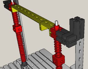
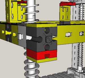
The following detail view will help you assembling the region around the switch (and the other corners, which look very similar). The switch will later act as the lower z axis end stop.
Phase 2
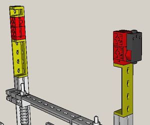
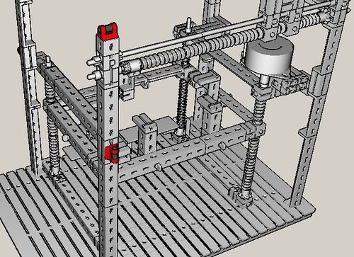
The second phase completes the frame for the z axis lifter: the rods (200 mm long) stick loosely in the lower holed bricks (part no. 36), initially held by their weight, later fixed by upper holed bricks.
Start (from the bottom) with a clamping bush, a bevel (part no. 35112) and a clampable worm (part no. 37858), then add normal worm elements (part no. 37858). The clamping bush will lift the bevel a bit, thus preventing the chain around all four "thread rods" from sliding over the other fischertechnik parts.
The topmost element of every worm gear is a "normal" worm element (part no. 37858), all elements are fixed in place by the upper holed bricks and a clamping bush (above the brick).
The black bricks are used to fix the rods in x/y-direction:
Do not forget to screw in the worm nuts before you mount the upper holed bricks or you will have to disassemble the frame again.
As soon as the second phase has been completed, you should span a chain around the black gears at the bottom of every rod - and around the small rod in the middle of the plate. Do it in a way which allows you to tighten the chain by moving the bricks with the rod along the slot in the base late. Move them inwards to tighten the chain, and outwards to loosen it again.
Do not tighten the chain too much: it should still run smoothly.
Phase 3
During the third phase, z axis lift and z stepper are assembled.
Detail views from every side illustrate how to construct the z axis lift. Make sure, that all worm nuts are on the same level before connecting them through the frame - you might have to loosen the chain a bit in order to turn each worm gear individually. In the end, the lift frame and the x- and y-axes (which will be constructed soon) should be exactly parallel.
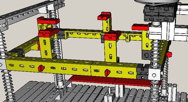
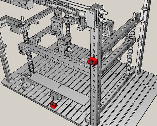
The glass plate which forms the basis for the hot glue printouts is loosely placed on-top of five elements which are mounted around the z lift frame - the following detail view shows how to assemble them.
Later, after the initial setup, a test print will show, how precise the base plate has been positioned - and you will have to compensate any deviations with thin paper sheets and/or adhesive tape on the red "brick 15x30x5 with slot and plug" (part no. 35049).
The following image shows the stamps which press the z axis end stops. Shown is a suggestion by the author - depending on your actual construction (especially the balsa wood cabinet for the heating unit) you might have to vary the assembly slightly.
It is time to mount the z axis stepper, the following images show you how. If you do not know how to handle stepper motors, you might look into part no. 79015 (hints for the stepper motor)
You should now also assemble the cover which protects the chain from drops of hot glue (the origin of the FTIStrap is in the corner with the z axis end stops).
Phase 4
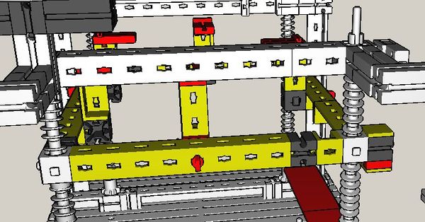
Step four extends the outer frame and prepares it for the x axis rods.
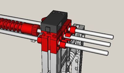
Two rods will be required on each side to carry the weight of the y axis mechanics, the extruder and the extruder feed - a single rod would bend too much.
Phase 5
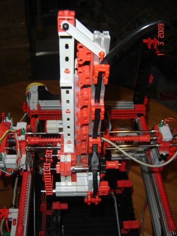
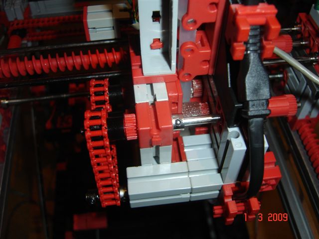
The fifth step adds the x axis mechanics and the beginning of the x axis slider. Clamping bushes at each end of a rod and on both sides of a brick prevent the rod from sliding back and forth. And a chain (which is not shown in the model) connects both thread rods to let them rotate simultaneously.
The following photographs illustrate how to attach the chain:
The following images show the corresponding fischertechnik model:
The rod end next to the stepper is the only one where no clamping bushes are needed.
After assembling the x axis mechanics you should manually check that everything runs smoothly.
Phase 6
This step illustrates how to construct the y axis mechanics and the stamps for the x axis end stops.
As usual, clamping bushes at the end of every rod prevent it from sliding back and forth.
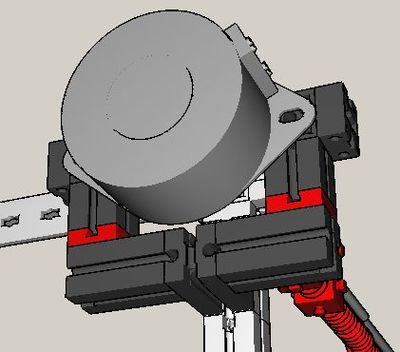
The stepper drives the y axis directly. Again, note the clamping bushes.
The next two pictures show the x axis stamps which actuate the corresponding end stops. Depending on you actual set-up, you may have to modify the stamps slightly.
Phase 7
Step seven deals with the y axis slider and the y axis stamps
Phase 8
Step eight begins with the construction of the feeder mechanics
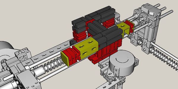
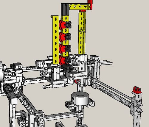
Note the yellow plates (part no. 38236): some of them are used to guide the hot-glue sticks, others adjust the distance between adjacent parts. Later, the red bricks with holes will guide rods for the feeder mechanics.
Actually, you are now constructing the left half of the feeder - you will soon start with the right half.
Always watch out for "flute pins" and "connectors": the construction is somewhat difficult as the usual fischertechnik raster had to be left - and some parts need to be slided around a bit in order to adapt to the actual size of extruder and hot-glue sticks.
Phase 9
This phase deals with the right half of the hot-glue stick guide
Agian, note the yellow plates:
Phase 10
This build phase concentrates on the feeder mechanics.
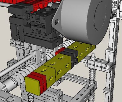
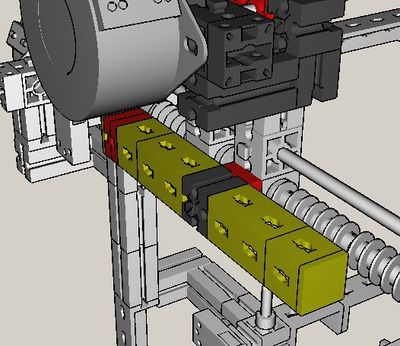
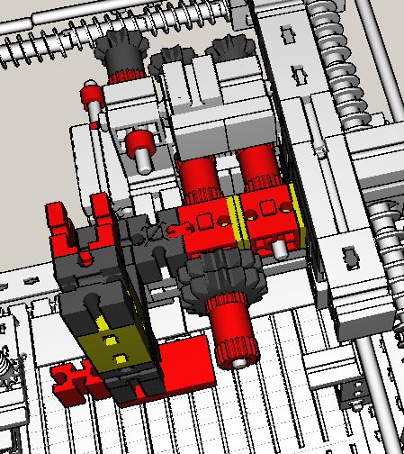
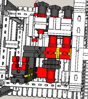
It looks a bit complicated because the roll threads (which finally squeeze the hot-glue sticks and move them forward into the extruder) did not fit into the fischertechnik raster. As a consequence, it was impossible to design a simple drive based on cogwheels only. Instead, a chain was used that is drawn around the cogs which finally drive the roll threads for the hot-glue sticks - the following picture should illustrate how the chain has to be attached. The upper cog is simply used to turn the chain round - and below (the rightmost rod on the picture) there is a simple rod which turns the chain round again: the rod itself is fixed, two clamp brushes guide the chain which simply slides around the rod.
The next foto was taken in order to show the roll threads for the hot-glue sticks (note that they are covered with sand paper to enhance friction) and illustrate how the power cable of the heating element is guided around the feeder (away from the mechanics)
A small hint: if you cover the roll threads with sandpaper, do not cut that into a rectangular shape but into a bevelled one (as shown in the next picture). This will help when you glue the sandpaper onto the roll and avoid areas where no sand is available to grab a hot-glue stick.
Here you see the associated fischertechnik model:
The next picture shows the parts which do not belong to the actual mechanics but will later guide the power cable of the extruder and prevent it from disturbing the mechanics.
Three bevels and a simple metal rod are used to guide the chain:
Here you see the associated fischertechnik model:
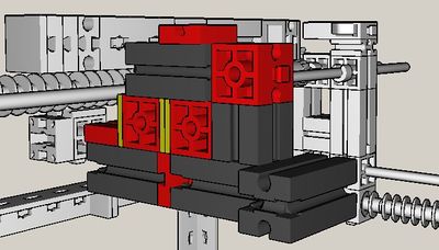
Fortunately, it turns out that two yellow plates between the holed red bricks sufficiently adjust the distance between the roll threads - provided that you also use hot-glue sticks with 7mm diameter!
The two roll threads which actually drive the hot-glue sticks should be covered with rough sand paper in order to increase friction. The lower part of the next picture again shows the two cogwheels which (together with a worm element) form the gear that allows the stepper to drive the roll threads.
Phase 11
At a first glance, it looks as if phase eleven would construct simple guides for hot-glue sticks (actually, that guide forms kind of a "reservoir" for the sticks), the power cable of the heating element and some cables only - but it also adds the stepper motor for the feeder.
Later, you will have to attach quite a number of cables. Therefore, it is a good idea to provide some guides which prevent the cables from disturbing the mechanics or even touch the nozzle of the hot-melt gun
Construction of the other guides is rather simple. But note that the red roller brackets can (and have to!) be moved horizontically such that a hot-glue stick easily slides through them and falls directly into the inlet of the extruder. Look down along the "channel" formed by the roller brackets and adjust them properly.
Last (but not least), you should mount the stepper for the stick feeder. The following foto shows the construction from below(!)
Phase 12
It is now time to assemble the bracket for the heating element and attach the connector plugs to cable the machine - the pictures below show you where to place the connectors:
The way of mounting the bracket allows for shifting it into the proper position (such that the inlet of the heating element is placed exactly under the feeder and the hot-glue sticks slide directly into the inlet).
Just to note it: of course, you should not mount an empty bracket but use the balsa wood cabinet you prepared before. Glue the cabinet into the bracket - if you haven't done so already - and mount everything (after the glue has hardened)
If need be, you might reduce the number of plugs needed to connect the steppers: the pictures always show two plugs per stepper wire (and each stepper has four wires, resulting in eight plugs per stepper or 32 in total) - one is screwed with the cable that stems from the stepper, the other one is screwed with the cable that connects the stepper with the fischertechnik interface. However, you may also screw both wires with one plug (as the author did himself) and save the other one.
Phase 13
In the final step, the fischertechnik interface and its extension box are attached to the model.
The two mounts are not really needed, but they hold the boxes in a position that allows for easy observation and operation.
After finishing this step, you are ready for cabling the machine.
Phase 14
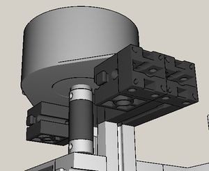
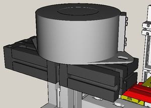
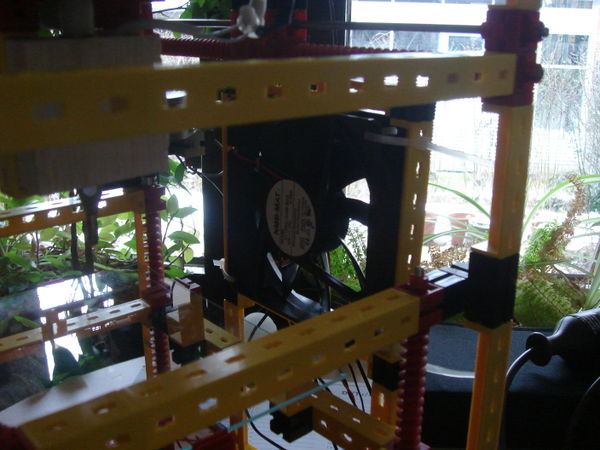
If you look at the photographs of the actual machine carefully, you will recognize one item which is still missing: the fan. The following two photographs show how the author mounted his fan:
A fischertechnik designer model of the fan bracket does not yet exist - however, it should not be too difficult to build one yourself from the photographs.
The fan helps cooling the hot-glue when another layer is to be printed without explicitly having to wait for the previous layer to harden first. Additionally, it can be used to achieve interesting "glitter" effects.
Check easy Movement along all Axes
Using fischertechnik parts for constructing a 3D printer is not really a professional approach. Thus, it is very likely, that your thread rods are not exactly parallel. Additionally, the plastic parts suffer from more friction than metallic parts would.
For that reason, you should first check for easy movement along all axes and, if need be, align all rods and reduce friction by means of a little bit of silicon oil.
After the inital set-up, you will run a test print which checks if your assembly "looses steps" in x-, y- or z-direction.
Cabling
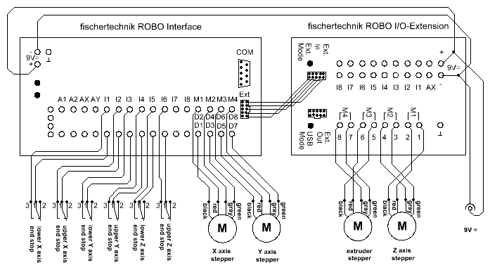
The following diagram illustrates the FTIStrap cabling:
Power Supply
Both the ROBO Interface and the ROBO I/O Extension box need 9V power. If you don't use a fischertechnik PowerBlock, you may also buy an ordinary 9V (switching) power supply. Connect both interface boxes with power.
Connection between ROBO Interface and ROBO I/O Extension Box
The ROBO I/O Extension box is needed to drive more than two stepper motors - connect the interface boxes with a ribbon cable as indicated in the diagram.
Connecting the Steppers
Each stepper has four feed wires, coloured red, black, grey and green. Two motor outputs (i.e. four digital outputs) drive a single stepper - connect the stepper wires with the digital outputs as shown in the diagram. If you just mix red and black or grey and green, the stepper will run in the opposite direction and you have to switch the mixed cables.
Connecting the End-Stops
Connecting the various end-stops is simple: connect the lower x-axis end-stop with I1 and the upper x-axis end-stop with I2. Use socket 2 and 3 of the fischertechnik switches and connect them to any of the two sockets of a digital input at the interface. Use the same approach to connect the lower y-axis end-stop with I3 and the upper y-axis end-stop with I4. Finally, connect the lower z-axis end-stop with I5 and the upper z-axis end-stop with I6.
Driver Software
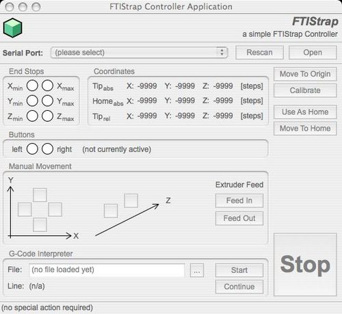
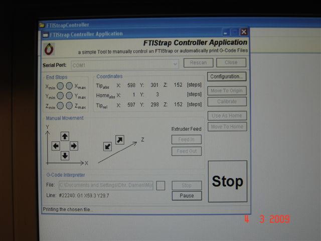
The "FTIStrap Controller Application" provides everything you need. It can be used
- to test and calibrate your set-up
- to move the FTIStrap manually
- to load and evaluate G-Code files
It won't get an award for its user interface but should still be intuitively usable
(tbd)
Initial Startup of the FTIStrap
If you have not done so, start the "FTIStrap Controller Application" - it will be used to test and calibrate your set-up.
Choose a serial port and "Open" it - make sure that the chosen serial port is connected to the ROBO Interface and the interface is running in "online" mode (i.e., after powering on the interface and upon completion of the built-in self-test, press the interface's "Port" button for more than five seconds - as soon as the "COM" LED is the only one blinking, the interface is in "online" mode)
If you add the serial port after having started the "FTIStrap Controller Application", you may have to "Rescan" in order to be able to choose the newly added port.
Check the End Stops
First of all, you should check the proper operation of your end stops - this includes a test of (a part of) your cabling and the proper communication between your PC and the fischertechnik interface.
Start with the lower x-axis end-stop: press it and watch the display on the PC screen. If the associated indicator of the controller application becomes red, the end-stop is functioning properly and you may proceed. If another indicator lights up, you mixed some wires - check your cabling and try again until only the expected indicator reacts.
If nothing happens on the screen, try another end-stop: if any switch causes a reaction on the screen check the cabling of the switch you are currently testing (or even try another one: your's might be broken)
Check the other end-stops in the same way.
Check the Steppers
Now, you are ready to test the proper operation of any steppers - this includes a test of the remaining part of your cabling.
But before, make sure, that none of the end stops is touched by any part of your machine - it is important that the steppers can run free for a few centimeters, at least. Also, do not "load" the feeder with hot-glue sticks yet.
The buttons in the "Manual Movement" group allow to move any of the steppers manually - a single click on any button moves the associated stepper one step forward or backward, respectively.
Start with the x-axis stepper: press the button with the right pointing arrow and watch the x axis stepper - it should move a bit. If you didn't recognize and movement, simply try again. After several clicks, the x-axis slider should have moved forward - should it have moved in the other direction, simply switch the plugs of D1 and D2. Please note: the very first click on the movement button of any axis may move the corresponding stepper in a different direction than expected. This is a side-effect of the way steppers work - don't worry. From the second click on the stepper should move as desired - if not, now is the time to worry!
If you do not recognize any movement, check the cabling and correct any errors. It is really unlikely, that one of the other steppers will move when you expect the x-axis stepper to do so: in that case, your cabling would be horribly wrong!
If you still do not recognize any movement, try to move any of the other steppers - the stepper you are currently testing might be broken (or the digital outputs might be). In the case of a shortcut, you might also have overheated the interface - in that case, wait a minute for the interface to cool down (and hope that you did not break it!)
Do the same for the other steppers as well (as the stick feeder is still empty, it is also safe to test the extruder stepper). If the y-axis stepper moves in the wrong direction, just switch D5 and D6 on the ROBO interface. If the z-axis stepper moves in the wrong direction, switch D1 and D2 on the ROBO I/O Extension box; if the extruder stepper moves in the wrong direction, switch D5 and D6 on the extension box.
Check the Printing Region
Next, you should verify, that the printing region is unobstructed.
First, move the x-axis slider along the whole x-axis, from one end-stop to the other. Whenever you reach an end-stop, you should hear a gentle "click" sound - make sure, that the slider can move the whole way without any hindrance. If any part collides with another one, you may either have to check your assembly or extend the x-axis stamp such that the corresponding end-stop is touched before the collision occurs.
Do the same for the y-axis.
Before checking the z-axis, place the glass plate on the foreseen brackets. Now, move the z-axis lift up until the plate is approx. 0.5 mm beneath the nozzle of the former hot-melt gun. Adjust your assembly such that the z-axis stamp touches the "lower z-axis end-stop" when the nozzle is at this height above the glas plate - you may use several sheets of paper or thin paperboards and adhesive tape for that purpose. This procedure may take a while but it is important for a good quality of the first layer of a printed object as the distance between nozzle and glass plate defines the thickness of the base layer.
Now test the z-axis for any obstructions as described above.
After successful completion, it is safe to let the FTIStrap run automatically.
Move into the Origin
Let the driver now move the system into the "origin" (i.e., the smallest possible x-y-z coordinate) by pressing "Move To Origin". Depending on the actual position of the FTIStrap it may take a couple of seconds until the origin is reached - but finally, the machine should stop and the three end-stop indicators Xmin, Ymin and Zmin should become red.
If you observe the coordinates display, you may recognize negative values first - this is ok. Upon a successfull move into the origin, all coordinates should have been reset to zero (and the controller should know which specific motor step corresponds to the zero coordinate).
Calibrate the System
Now press "Calibrate". The FTIStrap will again move into the origin and - from there - move to the opposite corner, counting the steps needed to touch any of the upper axis end-stops. It will take a couple of seconds but, in the end, the three end-stop indicators Xmax, Ymax and Zmax should become red - and, from now on, the application should allow browsing for a file to be printed (because the system is now "calibrated")
Press "Configuration" (which opens the configuration dialog) and save the current configuration - this prevents you from having to calibrate the FTIStrap every time you switch it on: just load a previously saved configuration instead. From now on, you will only have to recalibrate the system whenever you modify the assembly, or when you think, that some steps were lost during an earlier configuration run (e.g. because of excessive friction).
Check for lost Steps
Press "Move to Origin" again - and observe the coordinates display. First, the extruder moves into the x/y origin - afterwards, the z axis lift is moved to the zero position. When the extruder stops, the x and y coordinates should have reached zero - if not, the given (absolute) number of steps were lost, at least. A positive number indicates lost steps on the way back to the origin, a negative one lost steps on the way to the uppermost position.
Observe the z coordinate display when the z axis lift is close to its end-stop: the final coordinate is shown for a short time only, before it is set to zero.
Loosing a single step (per axis) might be ok (depending on how precise you want your prints to be), but if the (absolute) number of lost steps exceeds one you should check your assembly: lost steps indicate that the steppers are overloaded, usually due to excessive friction, hopefully not because of an improper (badly aligned) assembly. If need be, use a little silicon oil to reduce friction along the thread rolls (but take care that nothing of the oil reaches the nozzle of the hot-melt gun!)
And do not forget to observe your cabling when calibrating the machine: do any cables hinder the mechanics? Do the steppers have to pull their feed wires? What about the power cable of the heating element: does the machine have to pull the power cable or is it hanging down loosely? Watch out for everything that could be a reason for an additional load on the steppers!
Then "Calibrate" and "Move to Origin" again to see if the FTIStrap now moves as foreseen.
Check the Hot-Melt Gun (and the Fan)
It is now time to heat up the hot-melt gun and fill it with glue for the first time.
Thus, energize the heating element and wait a few minutes. In the mean time, you may slide a first glue stick into the feeder and - using the Controller Application - move it down until it reaches the silicon guide.
As soon as the heater has reached its target temperature, move the stick down fast for another two centimetres and then slowly further. Watch the casing while doing so and stop as soon as the casing seems to bend away due to the pressure of the feeder - in that case, just wait until the casing bends back and continue. Sooner or later you should see the first drop of hot glue being pressed through the gun's nozzle.
Now, the heater element has been successfully filled with hot-glue.
You should now also check the fan (if you have one) - just to be sure it works.
Check the Base Alignment
It is very likely, that your glass plate is not exactly parallel to the x-y axes. This is checked by printing a large (but thin) grid over the whole glass plate. From the results of that print you get information about where to lift the plate (e.g. by means of one or several layers of paper and/or adhesive tape) and whether glass plate and rods are straight enough (or whether they bend because the extruder and its feeder are too heavy)
Download the following file: BaseAlignmentTest.g
Print it to check the base alignment of your FTIStrap assembly. At first, the file will produce a "starting lane" for the extruder in order to guarantee a constant glue flow. Then it will print two broad lines both in x and y direction.
Look at the printout: the base plate is properly positioned if all lines are approx. 2mm thick. Broader lines indicate that the extruder nozzle is too close to the plate, thinner (or even discontinuous) lines show you that the nozzle is too far away from the plate.
Note: it is ok, if the printed lines are slightly thicker in their middle and thinner at their ends - this happens because the metal rods carrying the extruder bend a little under its weight: thus, the nozzle is closer to the plate in the middle of the x or y axes and farer away at the axes' ends. This effect occurs at the lowermost z level only - if you can live with it, you should only care about the line ends (or the corners of the printed rectangle, resp.). Otherwise, you will have to look for a construction that is more rigid...
Adjust the height of the plate and/or the z-position of the lower z axis end-stop and print the file again until the pattern on the plate looks ok.
You are now ready to start your first print.
Operation Manual
(tbd)
Tips and Tricks
Hot-Glue handling
Quite often, people using hot-glue for printing complain that they were unable to remove their objects from the base plate they printed on - the author never had these problems. The possible reason for successful printing might be:
- a glass-plate is used as the base to print on
- just before printing this glass-plate is wiped with a "multi-purpose anti-static" cleaning cloth which is usally used to clean computer monitors, mobile phones and other devices
- after printing, the object may then be vertically detached from the plate (perpendicular to the base layer) - detach with a bit of care, but it usually gets off easily
How to find out when the Heating Unit has reached Operation Temperature
You do not need any special equipment in order to find out when the former hot-melt gun has reached its operation temperature. Just use the following technique:
- move the FTIStrap into its origin
- move the nozzle up manually, until it is approx. 2 mm above the base
- if you have not done so already, power on the heating unit
- now wait until a first drop of hot-glue comes out of the nozzle
- "Feed In" manually approx. 8 times to compensate for the lost glue (if you did not pay attention and the drop became too large, "feed in" more often)
Now the system is ready for printing!
Never let too much hot-glue drop out of the extruder! You would end up with air bubbles in the reservoir of the heating element which would result in (relatively long) interruptions of the hot-glue flow during printing. If you do not want to stop heating (e.g. while looking for a file to print) move the FTIStrap into its origin and let the glass plate stop the glue flow a bit.
Note: interruptions due to air bubbles in the hot-glue reservoir will not appear immediately but only after several minutes of successful printing! Thus, the author's technique of printing a "starting lane" prior to the actual object does not help in this case!
Finishing printed Objects
From time to time it may happen, that printed objects are not of the foreseen quality. Usually, the reasons for a misprint are (besides forgetting to fill in more hot-glue sticks) step losses or bubbles within the hot-glue flow. In the author's understanding, it is not easy to keep the principal quality of the print-out while manually modifying it - normally, you should not try more than just cutting away excessive hot-glue (which dropped from the nozzle while it was moving to another position).
However, if it is still necessary to fill holes or notches, you should try that with another hot-melt gun (ideally of the same type as in your 3D printer). You may use the hot nozzle to manually plane the object's surface while filling in hot-glue where necessary. Undesired glue filaments may be washed away using warm water with a bit of soap or rinsing agent.
(tbd)
Modelling with Art-of-Illusion
(download, installation, required and/or recommended scripts, how to construct a cog, boolean operations) (tbd)
From STL to G-Code - the RepRap Host Software
(download and installation of the RepRap Host Software, recommended settings for the FTIStrap, hints for operation) (tbd)
Material Recycling
3D printers may also have some nice ecological side-effects: you may use them to "repair" broken devices - and you may reuse the material of failed prints and printed parts which are no longer needed.
The author is currently experimenting with an approach to cast his own hot-glue sticks - more to come soon...
(tbd)
Software Downloads
The "FTIStrap Controller Application" has been developed with REALbasic on an Apple Macintosh running MacOS X - but it is also available for Windows XP and Linux x86.
Warning: this is a very first version of the FTIStrap Controller Application - and has known bugs! Use it at your own risk - although it should mainly do what it is designed for
Windows XP
Just download FTIStrapController.zip and un-ZIP it into a directory of your choice - do not change the directory hierarchy within the archive (REALbasic needs the library in the sub-directory). Start the application with a double-click on the .EXE file.
The application has been tested under Windows XP, but not (yet) under Windows Vista.
MacOS X
Just download FTIStrapController.app.tar and un-TAR it into a folder of your choice. Start the application with a double-click on the .APP file.
Linux
Just download FTIStrapController.bin - but beware: the Linux version is completely untested!
Example Objects
Here are the G code files for some of the objects shown on this page, which have been printed with the FTIStrap
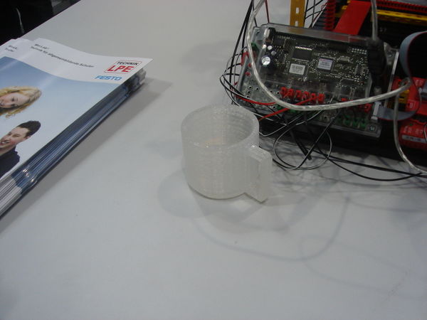
- Cup.g - a small coffee mug (without handle) Warning: it will take approx. 10 hours to print this cup!
- CupHandle.g - the handle for the coffee mug (you have to fix it manually)
- Funnel.g - a small funnel orignally "ordered" during the didacta 2009 fair in Hannover
The following files are made by Laserman:
(to enlarge click on the picture)
(for download right-click on the file and then "Ziel speichern unter..." / "save as...")
Settings (configuration) in the FTI-Strap controller:
timing = all set to 25
feed ratio = set to 40...50
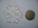
Snowflake.g - G-Code
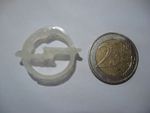
FT-fish.g - G-Code for the fischertechnik fish
Mercedes.g - G-Code
Mitsubishi.g - G-Code
Opel.g - G-Code
Peugeot.g - G-Code
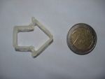
Arrow.g - G-Code
Roccat.g - G-Code
VW.g - G-Code
Cube.g - G-Code
Modifications and Extensions
The current design is far from being perfect and was often motivated by the parts the author had at home while constructing the system. However, one of the most important advantages of using FischerTechnik was (and is) the ease with which new variants can be built and tested - sometimes, it takes only minutes to realize an idea and see how it works.
For that reason, the FTIStrap is the ideal platform for testing alternatives. Among the supposable modifications and extensions are:
- enhancing the stability of the whole construction
- the integration of different extruders
- provisions for two (or even more) extruders
- any kind of approach to handle overhangs
Additionally, it is quite straightforward to
- control the heating element and/or the fan by the host
Enhancing the Stability of the Construction
Currently, the FTIStrap is built from plastic parts only - an approach which works reasonably well (especially, as the driver software takes care of many shortcomings such as friction and vibrations).
On the other hand, FischerTechnik also offers aluminium bricks which are more rigid than other parts (not only because of the material but also because they combine several connected bricks into a single, longer one). If you just replace plastic components by aluminium bricks (where possible) you will enhance the stability of the construction and reduce vibrations during the print.
As a consequence, you might be able to speed up printing (by modifiying the relevant parameters) or apply other modifications (see below) which require an enhanced stability.
Integration of different Extruders
At the moment, the design of the FTIStrap does not foresee an exchange of the extruder - extruder, feeder and y-axis slider are tightly connected to each other. The installation of another extruder would first require the disassembly of the current one - and then you might even have to modify the slider before mounting a new extruder.
On the other hand, it should not be too difficult to modify the design such that the extruder could be replaced without too much effort. Just take care that the modified construction does not become too heavy for the x-axis thread rods or you will have to modify them as well (e.g., by integration of aluminium bricks instead of plastic parts, see above)
It might be an interesting challenge to integrate the "standard" RepRap extruders into the FTIStrap frame - these are far more advanced than a simple "hot-melt gun". Or to integrate one of the syringe-based extruders preferred by the Fab@Home project. Just keep an eye on the overall weight of your construction when you try to use a different extruder.
Provisions for two or more Extruders
Mainly because of the size of the FischerTechnik base plate, the effective printing space of an FTIStrap is smaller than that of a RepRap (or of many other RepStraps). It would therefore be rather difficult to integrate more than a single extruder without reducing the printing space even further.
Overhang Handling
Without additional provisions, an extruder-based 3D printer is unable to print arbitrary overhangs - additionally, all printed objects have to start either on the base plate or (unlikely) on another object. The "Darwin" RepRap design tries to overcome this deficiency by means of another extruder which prints an (easily removable) "filler" to support any parts printed on top of it.
A potential alternative might be the "padding" of unprinted areas with some kind of powder before proceeding to the next layer, where the powder could then act as a support for the new print-out.
Events
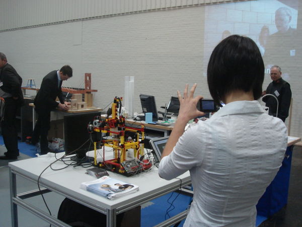
From Feb. 10 to Feb. 14, 2009, the FTIStrap has been presented on the "didacta 2009" fair in Hannover, Germany - the author had been kindly invited by the "LPE Naturwissenschaft & Technik GmbH" (see http://www.naturwissenschaftundtechnik.de). More than 400 visitors came to see the FTIStrap in action and learn about the underlying technology (and the RepRap project). Quite a few of them already announced to build their own copy of this model - let's see how many will actually do so.
Here are a few pictures taken during the fair
Copies of the FTIStrap
Here is the place where you can present your copy of the FTIStrap (fotos and/or text)
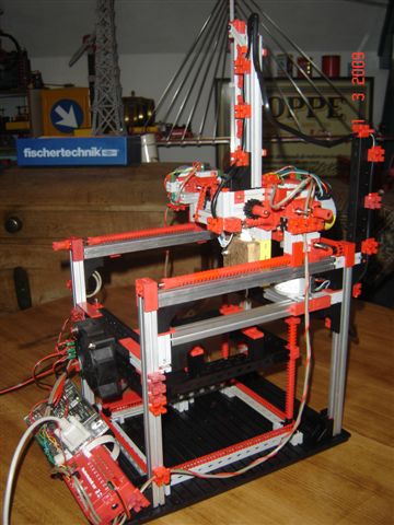
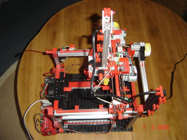
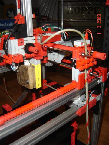
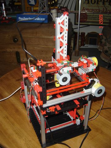
Andreas Guerten, Germany
Model build by Andreas Guerten from Germany:
I used self-modified Intelligent Interface (for flatband-cable) with Extension Module.
Note the 4 Aluminium Bricks at the 4 corners, which make the structure much more stable and rigid.
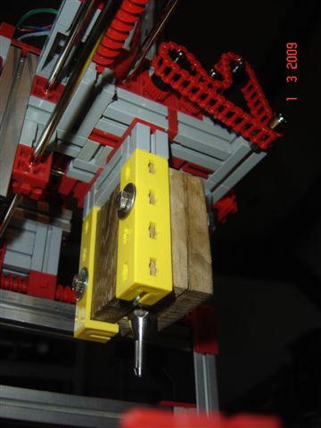
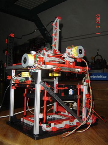
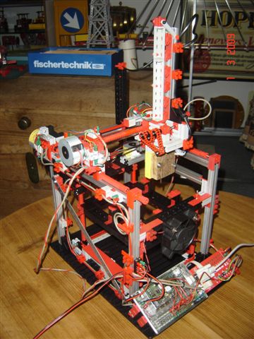
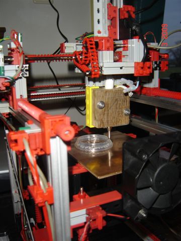
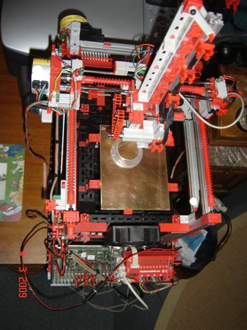
Peter Damen, Poederoyen (Netherlands)
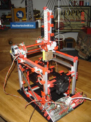
|
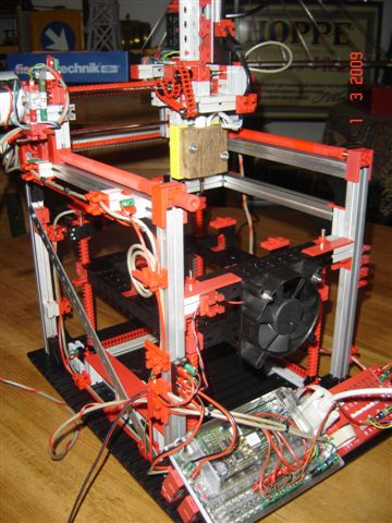
|
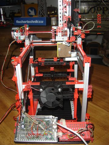
|
|
| |
|
|
| |
|
|
| |
|
|
| |
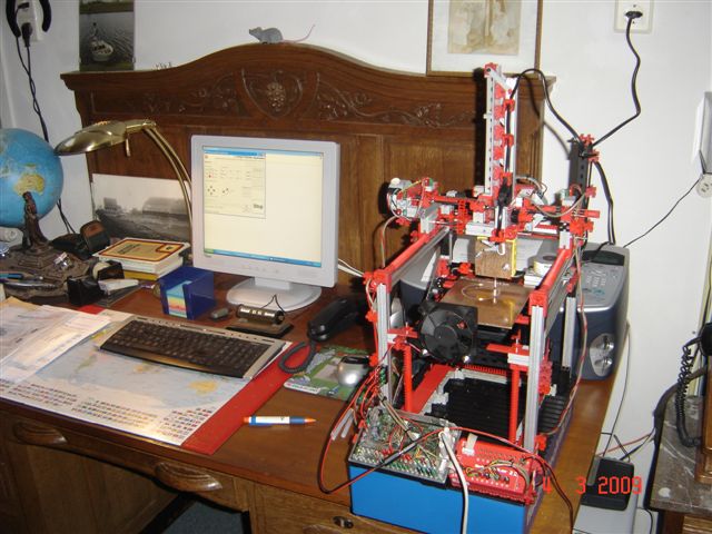
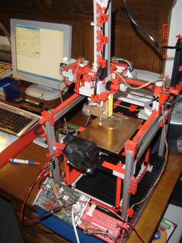
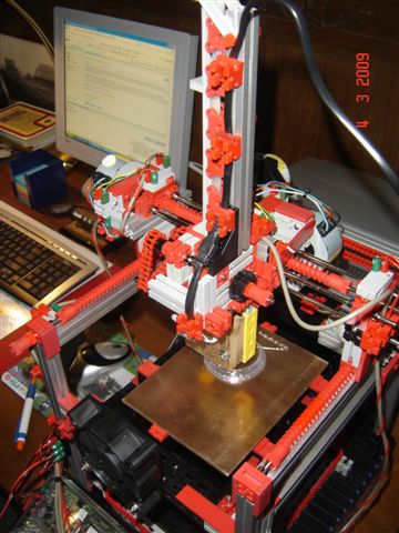
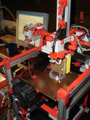
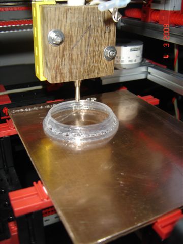
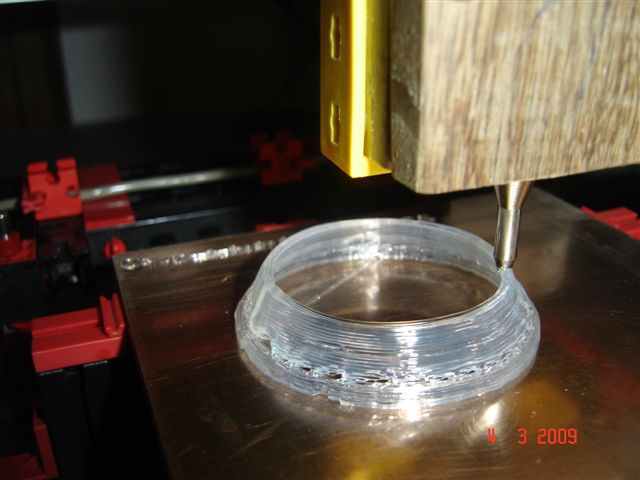
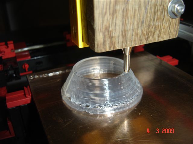
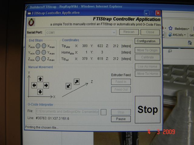
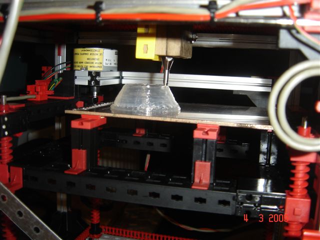
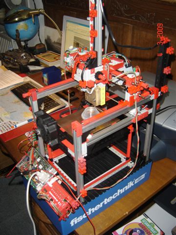
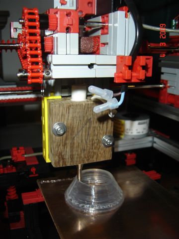
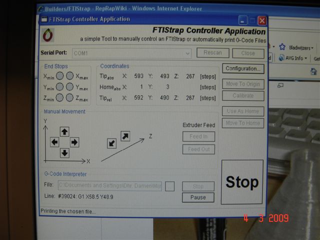
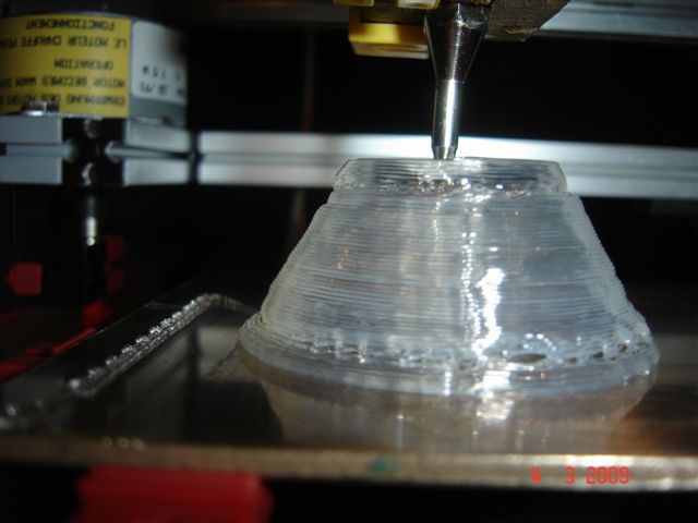
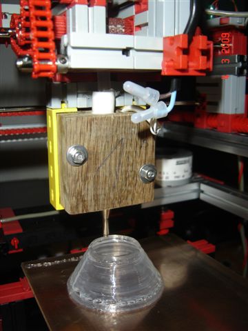
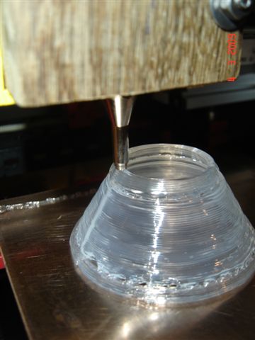
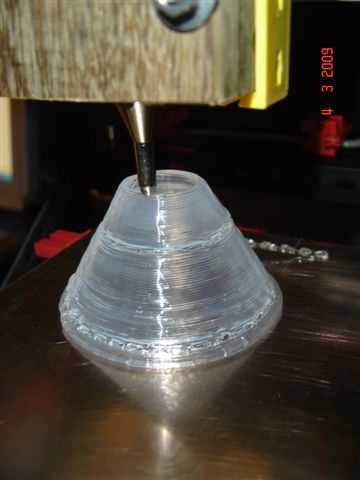
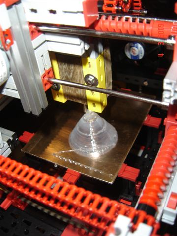
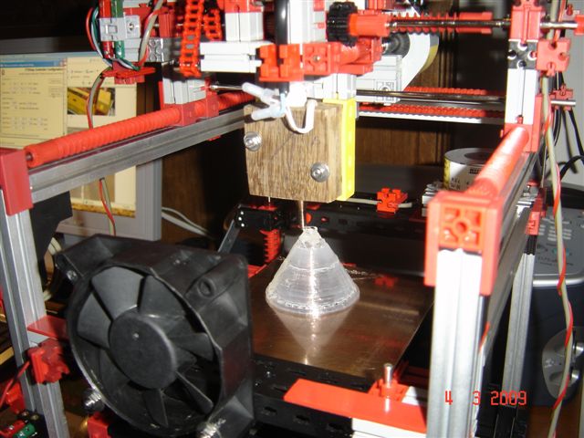
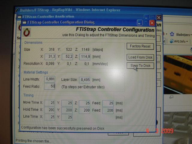
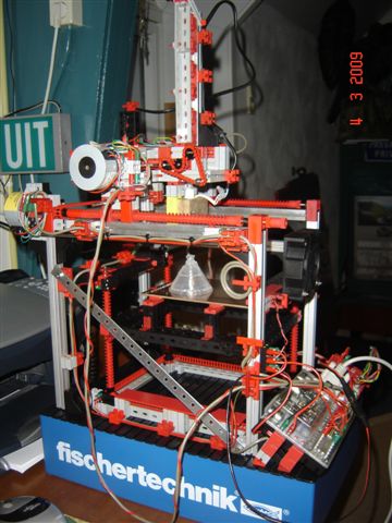
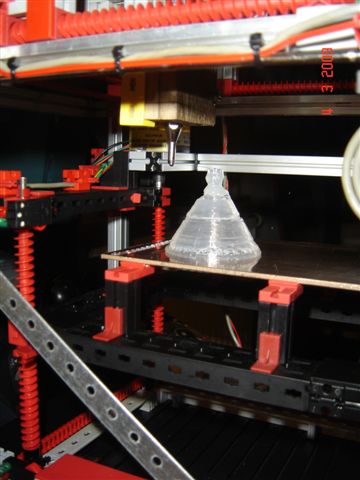
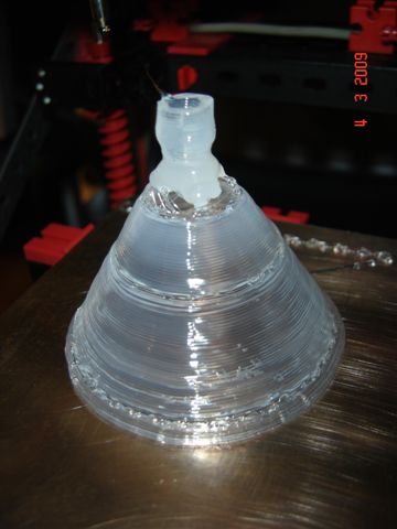
And here you see that printer in action (printing the "funnel" example object)
| |
|
|
|
|
| |
| |
|
|
| |
| |
| |
|
|
| |
| |
|
|
|
|
| |
| |
|
|
|
|
Who will come next?
Who will be the next one to complete a copy of the FTIStrap? Send me photographs of your assembly - or even better: just add them to this wiki page!
Future Plans
As usual, the author's activities suffer from his very limited time. For that reason, it is rather unlikely that it will be before 2009 that the FTIStrap takes the next step - the handling of overhangs (in any way). Currently, the author prefers the padding of unprinted areas with powder, but it is completely unclear if such an approach can be successful with hot-glue as print material.
Configuration File Format
The FTIStrap Driver saves several settings (and the results of a calibration run) in a "configuration file" which can be (manually or automatically) loaded prior to the first print after starting the driver. Currently, however, the file contains more information than can be entered through the Controller Application. Thus, it might be necessary to edit the file manually - here is its format:
(tbd)
References
- [1] RepRap - "Wealth without money..."
- (see http://www.reprap.org)
- [2] RepStrap - A Bootstrap RepRap machine
- (see http://www.reprap.org/bin/view/Main/RepStrap)
- [3] fischertechnik - Bausteine fürs Leben
- (see http://www.fischertechnik.de)
- [4] Knobloch GmbH - Wenn es um fischertechnik, Lehrmittel, Computer und Elektronik geht
- (see http://www.knobloch-gmbh.de/)
- [5] fischertechnik designer
- (see http://www.fischertechnik-designer.de/)
- [6] LPE Naturwissenschaft und Technik GmbH
- (see http://www.naturwissenschaftundtechnik.de/)
- RepRap forum -- FTIStrap - a RepStrap built from FischerTechnik parts
- http://forums.reprap.org/read.php?4,17008


