Universal Controller Board v1.2
This page describes something which is no longer the most recent version. For the replacement version see: UniversalControllerBoard 1 3
RepRap uses the same printed circuit design for both the stepper controllers and the extruder controllers, but different components (and some common ones) are needed for each. This page describes how to put the common components together on the PCB and test them.
In fact, there is very little extra that needs to be added to the PCB that you will assemble from the instructions on this page and the complete stepper controller so, as you will see below, you can use a stepper motor to test the board at this stage, even if the board is actually going to end up as an extruder controller.
- You'll need a soldering toolkit to do most of this.
- Read our Electronics Fabrication Guide if you're new.
- Please refer to the bill of materials for information on parts.
This basic board is used as the base of the standard V1.2 Extruder Controller and V1.2 Stepper Controller.
Contents
- 1 Build It
- 2 Technical
- 3 Future Plans
- 4 Building the Common Electronics for all the Control Boards
Build It
Oops! Board Bugs
v1.2.1 only
None yet! No connectors need to be flipped when constructing this board.
v1.2.0 only
This was our first experience with ordering bulk PCB's. There were a couple mistakes. We're very sorry. None are a big deal, more like inconveniences.
Drill Holes
The biggest one, is that the mounting holes did not get drilled and were marked in the wrong place. There are 3 spots on each corner of the board where they were supposed to go, but did not actually get made. Check the hole locations up against parts and drill the holes out with a 3mm or 3/16" drill bit. If you do this before you build the boards, it will be easier. As you can see from the photos, we found this out by trial and error...
TG GR Connector Flip Flop!
I didn't know what I was doing, and one of the transmit inputs is facing the wrong way. The best solution is to flip the GR connector around, so the header tab is facing the outside of the board as per the picture on the right. This way you make interchangeable, straight cables, and don't have to cross them.
No Silkscreen? No problem!
Aaah! For some reason, the last batch of boards did not have the proper silkscreen on them. We've contacted the manufacturer, and will make sure they always include it in the future. If you can't cope without, a temporary fix would be to follow the instructions on making your own PCB below, but instead do the toner transfer method with the silkscreen included in the board files on Sourceforge. Make sure you orient it correctly and put it on the right side.
-- Main.ZachSmith - 04 Jun 2007
Printed Circuit Board
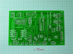
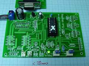
You can either buy this PCB from the RepRap Research Foundation, or you can make your own. The image shows the professionally manufactured Universal Controller v1.2 PCB ready for soldering. Its also cheap, only US$8.00. The component side has white markings on it, referred to as 'silkscreen', to tell you where to put the components and indicate which way round they go.
If you'd like to make your own board, please follow the v1.1 directions, as it uses an older design (but identical/compatible) that is more suited to home manufacture.
File Locations
You can download the electronics files from Sourceforge. This zip file contains the Kicad files, the PDF files, as well as the GERBER files you can use to build it yourself (or have it manufactured).
Soldering - first stage: power, PIC holder, communications and LED
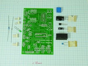
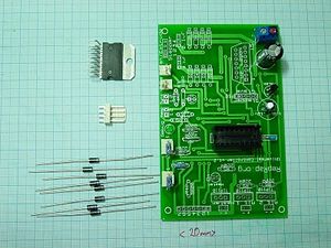
Here is a mise en place for the first stage of making the universal board:
Order of Assembly
- 18-pin DIL socket - if your holder has a dimple, match it up with the notch on the silkscreen
- U1, 78L05 regulator- match up flat side with silkscreen
- C1 (1000uF) - polarity on silkscreen
- C2 (100uF) - polarity on silkscreen
- Debug LED - the anode (+) is the longer of the two leads and goes in the square pad.
- R2 (10K), R4 (220R), C4 (0.1uF) - the orientation doesn't matter.
- Double screw terminal for power - make sure to put the openings for the wire facing the outside
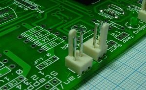
- Version 1.2.0: GR and TG 2-pin headers. TG: tab facing inside. GR: tab facing outside
- Version 1.2.1: Rx and Tx 2-pin headers. Both tabs facing inside
- "max" and "min" 3-pin connectors, the tab goes to the inside
- R7 and R8 - fit shorting wire links.
R7 and R8 allow the use of non-standard opto-switches and are usually not needed; replace them with wire jumpers. These can be conveniently obtained when trimming R2 or R4.
The PIC will eventually be mounted in the 18-pin DIL socket, as it will need to be removed and re-inserted for programming. Don't worry if you can't get the high-profile sockets used in the photos; ordinary 18-pin sockets will do just fine. Leave the PIC in its anti-static packaging for the moment.
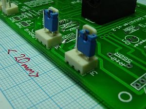
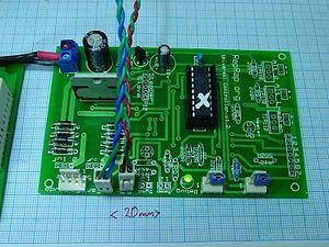
Use a couple of jumpers to short the left-hand pairs of pins of "Max" and "Min", as in the picture. In a stepper controller these connect the end-stop sensors, and shorting the middle pins to ground is the signal the the carriage is not at the endstop. In an extruder they are used to log the extrude speed and to check for the exhaustion of the material being extruded.
Testing Rounds
First test - power
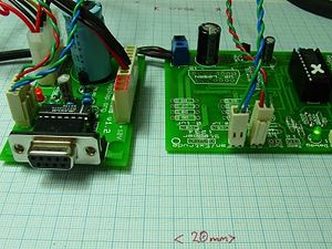
Wire the Communications and Power Distribution Board to your new circuit like this, but leave the PIC out of its socket, leave the transmit and receive wires disconnected, and do not connect the RS232 cable to the computer.
Take Great Care to get the polarity of the power leads correct. Do not be afraid to mark the positive connectors with red permanent marker if this helps you get it right. Check and double check the markings on both silkscreens. You will need to make crimped connectors for the Power/Comms board that terminate in raw wire for the Universal Boards.
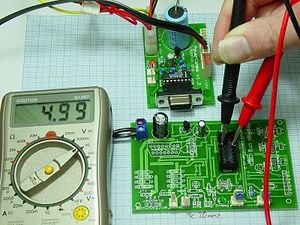
Finally, turn the power on and check that there is 5v between sockets 14 and 5 of the PIC holder (- to pin 5, + to pin 14). This 5v comes from the regulator U1 (78L05). If you can't get your meter probes into the socket to touch the pins, poke a couple of bits of wire in holes 5 and 14, and measure the volts on those.
Take the + probe of the voltmeter and check all the pin-sockets of the PIC connector relative to its socket 5. Most should be at 0v; one or two should be at about 3v. None should be more than 5v. Note that the LED should NOT light up at this point.
Switch off the power.
Second test - program chip
Now program up a PIC 16F648 (U3) with the file stepmotor.hex. This is the X-axis PIC control program for your RepRap machine. Observe the usual CMOS anti-static precautions when handling the PIC. Plug in the programmed PIC and mark it with an 'X' so you know which one is which when you come to build more boards. There is a notch on the silkscreen that corresponds to a notch in your chip. Make sure they are on the same side. You can also program the PIC while it is plugged into the board; to see how click here.
Switch on the power. The debug LED on your new board should light and stay on; it is instructed to do so by the PIC program so you know that much is working. Switch the power off again.
Third test - exercise command
Connect an RS-232 cable between your computer and the Comms board. Connect transmit (T) on the Comms board to receive (R) on your new board, and recieve (R) on the Comms board to transmit (T) on your new board. The RS-232 cable is not shown in the photograph right for clarity. On the Universal PCB, T is the left-hand connector, R is the right of its pair.Put shorting links between the middle pin and ground on the two 3-pin connectors beside the LED labeled Max and Min. The optoswitches that will form the endstops will ultimately be plugged into these, but the shorting links fool the PIC into thinking that it is at neither endstop, so it will drive the (so far non-existent) motor. The picture by the Fourth Test below gives a clear view of these shorting links (blue). Old CD or disc drives are a good source of such links.
Start the RepRap host software. Select File -> Preferences... and set the port to the one your RS232 cable is connected to. On Linux, if you're using a raw serial port it will be /dev/ttyS0 or /dev/ttyS1, otherwise if you're using a USB -> Serial cable, it will be something like /dev/ttyUSB0. Under Windows, the port will be COM1, COM2, COM3 or COM4.
Change the Geometry from 'nullcartesian' to 'cartesian'. Null Cartesian is a dummy RepRap machine inside the software for testing purposes. Cartesian is an honest-to-goodness real RepRap, such as the one taking shape on the end of your RS232 cable.
Click on OK in the Preferences box to save them.
Turn on the power.
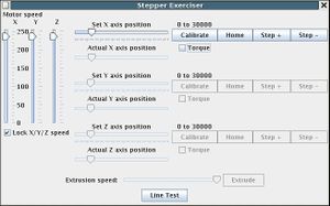
Now, select Tools -> Stepper exerciser. This should open a window that looks like this:
As you can imagine, this window allows you to move your RepRap machine around just by dragging those pointers with the mouse. Drag the X-axis pointer to the right. The LED on your new board (which was on continuously) should begin to flash. Whenever one of the stepper controllers is moving its motor it flashes its LED, and this is what's happening. Of course you don't actually have a motor connected, or even the motor driver, U2 (L298N). But the PIC doesn't know that.
Select the X Home button. The LED should flash again as the PIC seeks the home optoswitch. This "optoswitch" is just a shorting link at the moment, of course (the one nearest the LED). Pull that link off, and the flashing should stop as the PIC will think it's hit its end-stop. The X slider in the control window should also move to its extreme left-hand end, indicating home.
Close the program and all the windows, and turn off the 12v power. Take the PIC out of its socket and pop it back in its anti-static bag..
Soldering - second stage
Components for this stage (See the BOM for more detailed information)
| Component | Value |
| D1 - D8 | diodes |
| P9 | 4 pin header |
| U2 | L298N |
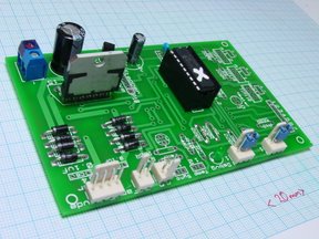
The mise en place for this stage is once more shown on the right.
Order of Assembly
- the 'stepper' header. tab towards inside of board.
- U2 -- do this before diodes... otherwise it will be hard to reach
- the diodes. Note the polarity of the diodes: the stripe / bar to the right in the picture.
We have successfully used 1N4005 and 1N4007 diodes with this design.
Testing Rounds
Fourth test - voltage reading
Reconnect the power connection to the Comms board, put a voltmeter on sockets 5 and 14 of the PIC holder (- to pin 5, + to pin 14), and turn on the power. The voltmeter should read 5v.
Take the + probe of the voltmeter and check all the pin-sockets of the PIC connector relative to its socket 5. Most should be at 0v; one or two should be at about 3v. None should be more than 5v.
Turn off the power.
Fifth test - LED Flashy
Plug the PIC back in.
Reconnect the transmit and receive lines. and re-run the Third Test above. The LED should still flash.
Turn off the power.
Sixth test - Stepper Action!
Connect a 4-wire RepRap bipolar stepper motor (follow that link for details, suppliers, and wiring) to the connector at the lower left of the picture (P9). In fact any bipolar stepper with a coil resistance of more than 10 ohms and less than about 50 ohms should work for testing if you don't have your RepRap steppers yet. If improvising with your own steppers, connect one coil between pins 1 and 2 of P9, and the other between pins 3 and 4. If you have no stepper motors at all, see the LED Stepper Tester.Plug the stepper motor socket onto the connector at the lower left, red wire towards the centre of the PCB. Open the Eclipse Java development program. Open the Reprap project, and walk down the tree: src -> org.reprap. Right-mouse click on main.java and go down to Run as... -> Java Application. From the File menu select Preferences, and from that select Axes. Set the X axis power to 100%, and click OK.
For all the following tests, don't run the motor for more than a few seconds because the L298N chip doesn't have a heat sink on it yet - it'll get hot. Between each test, uncheck the Torque box for the motor to turn the current to it off when it isn't doing anything.
Repeat the third test, but first drag the motor speed bars on the left of the window down to about two-thirds of the way. The LED should flash and the motor should rotate. A piece of masking tape or blu-tak and wire on the shaft will make the rotations of the stepper easier to see.
Finally, select the X-Axis "Home" button in the window. The motor should rotate continuously in the opposite direction.
Pull off the jumper on K2 (the one being indicated with the forceps in the photograph). The motor should stop as this is the signal to the PIC that the endstop has been reached.
Congratulations!
You have finished the common circuitry for the Universal PCB!
Continue on to making:
Technical
PIC 16F648 Pinout:
One obvious common component is the PIC - a 16F648. But some pins do different things in the two devices:
[i] = input, [o] = output, [b] = bidirectional
| Pin | Stepper controller | Extruder controller |
| RA0 | L298 [o] | L298 (Fan) [o] |
| 1 | Sync [b] | Thermistor [i] |
| 2 | L298 [o] | L298 (Fan ) [o] |
| 3 | Sync [b] | Heater [o] |
| 4 | LED [o] | LED [o] |
| 5 | Max [i] | Material out (input only) [i] |
| 6 | - | Thermistor [i] |
| 7 | - | Thermistor [i] |
| RB0 | Min [i] | Slotted-wheel for extrude speed [i] |
| 1 | Rx [i] | Rx [i] |
| 2 | Tx [o] | Tx[o] |
| 3 | L298 Enable [o] | L298 Enable [o] |
| 4 | L298 [o] | L298 (Extrude) [o] |
| 5 | L298 [o] | L298 (Extrude) [o] |
| 6 | - | - |
| 7 | - | - |
Board Modifications
R7 and R8 are only needed if you use an alternate design for end-stop, material-out, and extrude-speed sensors. Normally they are replaced by wire jumpers.
Without L298N
Components marked (A) are for an alternate extruder design without an L298N, and so can normally be left out. (This extruder is cheaper to make, but can't reverse the extrude motor - to make it just leave out U2, D1...D8, and P9, then add in these components.)
| R6 | 220R |
| R7 | 220R |
| R8 | 220R |
| R9 | 220R |
| Q3 | TIP110 |
| Q2 | TIP110 |
| P6 | CONN_2 |
| P7 | CONN_2 |
Slave Motor
It's also possible to drive a slave stepper from this board using another L298N chip. There is a connector (P10) for the slave stepper driver should you want to drive more than one stepper. P10 brings out all the signals from the PIC to the stepper driver, so just connect another L298N on a separate board up like the first one to those five signals (also don't forget the diodes) and plug in another stepper, which will run in synchronisation with the first.
Add your own electronics
The connector P11 has several of the PIC lines running to it and power (see the circuit diagram in KiCad). It is intended to allow users to experiment by adding extra electronics. If you want to do this, put a 7-pin connector in for P11, make up your circuit (stripboard is probably easiest), and put a 7-way socket on the board that will plug into P11.
Future Plans
This page has been flagged as containing duplicate material. An editor has suggested merging this page or section into Universal Controller Board 1.2. (Discuss)
Building the Common Electronics for all the Control Boards
RepRap uses the same printed circuit design for both the stepper controllers and the extruder controllers, but different components (and some common ones) are needed for each. This page describes how to put the common components together on the PCB and test them.
In fact, there is very little extra that needs to be added to the PCB that you will assemble from the instructions on this page and the complete stepper controller so, as you will see below, you can use a stepper motor to test the board at this stage, even if the board is actually going to end up as an extruder controller.
PIC 16F628 Pinout:
One obvious common component is the PIC - a 16F628. But some pins do different things in the two devices:
[i] = input, [o] = output, [b] = bidirectional
| Pin | Stepper controller | Extruder controller |
| RA0 | L298 [o] | L298 (Fan) [o] |
| 1 | Sync [b] | Thermistor [i] |
| 2 | L298 [o] | L298 (Fan ) [o] |
| 3 | Sync [b] | Heater [o] |
| 4 | LED [o] | LED [o] |
| 5 | Max [i] | Material out (input only) [i] |
| 6 | - | Thermistor [i] |
| 7 | - | Thermistor [i] |
| RB0 | Min [i] | Slotted-wheel for extrude speed [i] |
| 1 | Rx [i] | Rx [i] |
| 2 | Tx [o] | Tx[o] |
| 3 | L298 Enable [o] | L298 Enable [o] |
| 4 | L298 [o] | L298 (Extrude) [o] |
| 5 | L298 [o] | L298 (Extrude) [o] |
| 6 | - | - |
| 7 | - | - |
Circuit diagram and PCB
All the KiCad files for this are in ~your-id/workspace/electronics/Universal-pcb. In particular, if you open stepper-and-extruder.pro in that directory in KiCad you will have both the circuit diagram and the PCB layout available.
You may have acquired the PCB from a commercial supplier, in which case carry on below. To make one yourself, follow this link.
Here's what the PCB will look like when you start. The side the components go on is the one with the lettering (this one):
Soldering the first components onto the PCB
Complete components list
The file stepper-and-extruder.lst in ~your-id/workspace/electronics/Universal-pcb. is the component list created by KiCad, which you can use to order the parts you will need.
Ignore components J1 ... J8; they are just SIL connectors that were added to the circuit diagram to create the pattern for the breadboard area - you don't actually need to solder connectors into those holes (though you can if you want - then you can breadboard without soldering).
Here is the list, together with an indication of whether the component is needed for the stepper drivers (S), the extruders (E), or both (B). Components marked (A) are for an alternate extruder design without an L298N, and so can normally be left out. (This extruder is cheaper to make, but can't reverse the extrude motor - to make it just leave out U2, D1...D8, and P9, then add in the (A) components.)
R7 and R8 are only needed if you use an alternate design for end-stop, material-out, and extrude-speed sensors. Normally they are replaced by wire jumpers.
|
|
|
The connectors CONN_n are 2.54 mm pitch PCB transition connector pins like A here:
where n is the number of pins. One exception to this is P1, which should be a 2.54 mm pitch PCB screw connector like B. This is the 12v power connector.
Soldering - first stage
These are the first components to solder in:
| Component | Value |
| C1 | 1000uF 25v |
| C2 | 100uF 12v |
| C4 | 0.1uF |
| D9 | LED |
| P1 | CONN_2 |
| P5 | CONN_2 |
| P8 | CONN_2 |
| R4 | 220R |
| U1 | 78L05 |
| U3 | PIC16F628 |
Start by soldering in all the above components except the PIC (U3). The PIC should be mounted in an 18-pin DIL socket, as it will need to be removed and re-inserted for programming. Leave it in its anti-static packaging for the moment.
It can be hard to solder those components with flat bases that need to be soldered to the component side of the PCB. A good way to solve this is to tin round the hole where the component's leg is to go, then to tin the leg too. Now put the leg through the hole and touch the soldering iron onto the end of it sticking out of the bottom of the PCB. This melts the tinning and allows the component to be soldered in place. Alternatively, if the tinning on the PCB extends a bit beyond the periphery of the component, you can touch the soldering iron down there on the component side with the component a little proud of the PCB, then push it down when the solder melts.
Take particular care to get the polarity of the electrolytic capacitors and the LED correct. (The right-angled LED that I used and that you can see in the picture was the wrong way round; this is easily fixed by straightening its leads, turning it over in the holder, then bending them the other way.)
Here's what the board will look like when you've finished.
The red arrows indicate through holes. If you make the PCB yourself you will have to solder a short length of wire (a clipped component lead works well) through each of these. A commercial PCB should be through-plated and not need this.
First, second, and third tests
First test
Wire the Communications and Power Distribution Board to your new circuit like this, but leave the PIC out of its socket and leave the transmit and receive wires disconnected.
Take Great Care to get the polarity of the power leads (red and black on the picture, and with red + and blue - labels) right.
Connect 12v power to the Comms board and check that there is 5v between sockets 14 and 5 of the PIC holder (- to pin 5, + to pin 14). This 5v comes from the regulator U1 (78L05).
Take the + probe of the voltmeter and check all the pin-sockets of the PIC connector relative to its socket 5. Most should be at 0v; one or two should be at about 3v. None should be more than 5v.
Switch off the power.
Second test
Now program up a PIC 16F628 (U3) with the file ~your-id/workspace/firmware/build/16f628/stepmotor/stepmotor.hex. This is the X-axis PIC control program for your RepRap machine. Observe the usual CMOS anti-static precautions when handling the PIC.
Connect transmit (T) on the Comms board to receive (R) on your new board, and recieve (R) on the Comms board to transmit (T) on your new board. Plug in the programmed PIC, notch to the right in the orientation shown in the picture above.
Switch on the power. The LED on your new board should light. Switch the power off again.
Third test
Connect an RS232 cable between your computer and the Comms board.
Open the Eclipse Java development program. Open the Reprap project, and walk down the tree: src -> org.reprap. Right-mouse click on main.java and go down to Run as... -> Java Application.
Select Preferences from the File menu and set the port to the one your RS232 cable is connected to.
Click on the Axes tab and select Cartesian as the geometry. (The default is Null Cartesian, which is a dummy RepRap machine inside the software for testing purposes.) Cartesian is an honest-to-goodness real RepRap, such as the one taking shape on the end of your RS232 cable...
Click on OK in the Preferences box.
Turn on the power.
Now, from the Tools menu select Stepper exerciser. This should open a window that looks like this:
As you can imagine, this window allows you to move your RepRap machine around just by draging those pointers with the mouse. Drag the X-axis pointer to the right. The LED on your new board (which was on continuously) should begin to flash. Whenever one of the stepper controllers is moving its motor it flashes its LED, and this is what's happening. Of course you don't actually have a motor connected, or even the motor driver, U2 (L298N). But the PIC doesn't know that.
Close the program and all the windows, and turn off the 12v power.
Soldering - second stage
Remove the PIC and place it in its anti-static package.
The picture above shows the second stage of soldering complete. Start by putting links in the through-holes marked with the arrows. There is also a through-hole at B. This is a connector (P10) for a slave stepper driver should you want to drive more than one stepper off the board. But if you don't need that, just add the one through connector. Then add the links at A (in place of the optional R7 and R8).
Here are the remaining components needed at this stage:
| Component | Value |
| D1 | 1N4005 |
| D2 | 1N4005 |
| D3 | 1N4005 |
| D4 | 1N4005 |
| D5 | 1N4005 |
| D6 | 1N4005 |
| D7 | 1N4005 |
| D8 | 1N4005 |
| K1 | CONN_3 |
| K2 | CONN_3 |
| P9 | CONN_4 |
| R2 | 10K |
| U2 | L298N |
Solder in the resistor, the connectors, U2, then the diodes, in that order. Note the polarity of the diodes - bar to the right in the picture.
Put jumpers on connectors K1 and K2 as shown in the photograph (just above the letters A) - this tells the PIC that the axis that it thinks it is driving is not at either end stop.
Forth, fifth, and sixth tests
Fourth test
Reconnect the power connection to the Comms board, put a voltmeter on sockets 5 and 14 of the PIC holder (- to pin 5, + to pin 14), and turn on the power. The voltmeter should read 5v.
Take the + probe of the voltmeter and check all the pin-sockets of the PIC connector relative to its socket 5. Most should be at 0v; one or two should be at about 3v. None should be more than 5v.
Turn off the power.
Fifth test
Plug the PIC back in.
Reconnect the transmit and recieve lines. and re-run the Third Test above. The LED should still flash.
Turn off the power.
Sixth test
Connect a 4-wire bipolar stepper motor to the connector labeled C in the picture (P9). This can be one of the RepRap steppers that you will be using, or just a spare for testing taken from an old printer, say. Any stepper with a coil resistance of more than 10 ohms and less than about 50 ohms should work. Connect one coil between pins 1 and 3 of P9, and the other between pins 2 and 4.
Repeat the third test, but first drag the motor speed bars on the left of the window down to about half way. The LED should flash and the motor should rotate (put some sticky tape on the spindle so you can see what's happening).
Finally, select the X-Axis "Home" button in the window. The motor should rotate continuously in the opposite direction.
Pull off the left-hand jumper (on K2; the one on the left in the photograph). The motor should stop as this is the signal to the PIC that the endstop has been reached.
Congratulations! You have finished the common circuitry for the Universal PCB!
-- Main.AdrianBowyer - 01 Nov 2006
