Compliant Linear Motion Mechanism 1
Release status: Experimental
| Description | A prototype linear motion mechanism
|
| License | unknown
|
| Author | |
| Contributors | |
| Based-on | |
| Categories | |
| CAD Models | |
| External Link |
Introduction
This project is in the spirit of Fdavies's work on printable Sarrus linkages, such as Sarrus_L04 and Sarrus_Z02. The idea is to build a mechanism that creates precise large-displacement linear motion, without using precision mechanical components like ground metal rods, ball bearings, and so on. This page presents a design based on compliant mechanisms.
A compliant mechanism does not use traditional joints like pivots and sliding joints. Instead, motion is allowed by the elastic flexing of thin regions of material. There are a lot of researchers in this area, particularly in MEMS applications. The See Also section has links to some of this work.
This mechanism is well-suited for a fabrication process like Laminated Object Manufacturing. RepRap-style 3D printers will have trouble making the thin compliant sections without support material. However, it has been suggested elsewhere that these type of linkage mechanisms could be modified to use living hinges (see CalcBot Pen Holder by MBC for an example of a printed living hinge). As a far-out RepStrap idea, consider building motion stages from scratch by laminating sliced-up-recycled-soda-containers (plastic or aluminum).
Device Overview
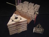
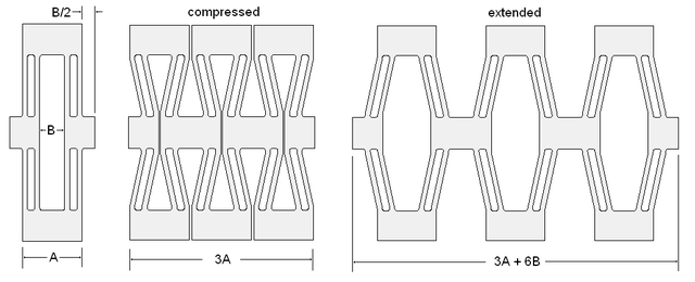
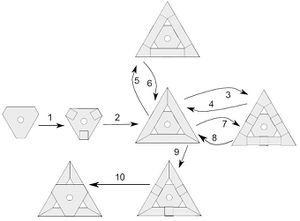
The device is based on a collection of little compliant sub-units analogous to a parallel 4-bar linkage. The sub-units are combined into a planar mechanism with large displacement (see figure). Three of these planar compliant mechanisms are then stacked up into a triangular prism. The photo shows mechanisms made from plastic, cardboard, and aluminum. The aluminum was too stiff to be useful and the cardboard too floppy. The plastic version worked well enough to test under motorized power, but is still not quite stiff enough to be useful as part of a fabricating machine. Careful optimization of the design is needed if it is going to be practical. The simple theory discussed below may serve as a starting point for optimization, and there are a lot of other resources out there (see 'See Also' section).
Construction
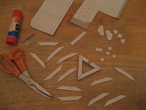
The aluminum version was made by etching and bending three separate plates that were then glued together with cyanoacrylate. The cardboard version was made with scissors and glue. The plastic version was made with laser-cut acrylic scrap (the flexural members are actually cellulose acetate butyrate because that's what we had sitting around, but acrylic should work fine). The plastic parts were cleaned with Loctite 770 primer, then glued together with clear silicone household caulk.
Templates in pdf format can be downloaded in the zip file. The zip also contains an OpenSCAD script of the compliant stack. The dimensions in the OpenSCAD are made up, so that file is for reference only. The actual dimensions of the real device (all in inches) are: flexural member thickness t = 0.015", width w = 0.385", length L = 0.6", module length A = 0.85", module deflection B = 0.24". See Figures for symbol definitions.
The leadscrew is a 10-24 threaded rod driven by a pulley, rubber band, and small DC motor. The large pulley has a captured 10-24 nut that drives the leadscrew. The pulleys have a small amount of crown to help keep the flat belt aligned.
Theory
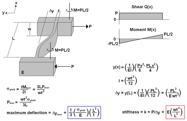
As a very simple first approximation, the Euler-Bernoulli beam equation can be used to estimate the stiffness of a compliant mechanism. A single flexural element is treated as a beam fixed at both ends and subject to loads as shown in the figure. After the spring stiffness for one element is found, the stiffness of an entire mechanism can be found by lumping together using the rules for combining multiple springs. Note: E is Young's Modulus in units of pressure.
This gives an estimate of stiffness in the axis of desired motion, so we want the stiffness to be low. The stiffness in and about the other axes we want to be high, but it is quite a bit more tricky to model the elasticity in those directions. Finite element analysis could be used to model the more general elasticity properties.
The expression outlined in blue above, for the maximum deflection, allows us to calculate how far a given flexure element can deflect before yielding. In practice we would want to stay below the yield point by a certain safety factor. Notice that one of the terms depends only on intrinsic material properties (ratio of yield stress to Young's Modulus), while the other term depends only on geometry <math>\left(L^2/t\right)</math>. So we have two avenues for design: we can select a desirable material that has a high ratio of yield stress to Young's modulus <math>\left(\sigma_{yield}/E\right)</math>, and we can design flexure elements with a high aspect ratio <math>\left(L/t\right)</math>. Of course, as these parameters are increased we have to worry about increased flexibility in undesirable modes as well (torsion, off-axis bending, etc). But the simple linear beam case is a good starting point for design.
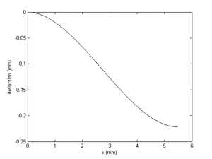
Here is a MATLAB script that calculates stiffness, maximum deflection, maximum load, and plots the elastic curve. The material and geometric properties match those of the etched aluminum device shown in the pictures. The plot output showing the form of the elastic curve is shown below the script.
% Yield strength of aluminum 2014-T6 in units of newtons/meter^2
yieldStress = 414E06;
% Young's modulus of aluminum 2014-T6 in units of newtons/meter^2
E = 73.1E09;
% beam thickness in meters
t = 0.254E-03;
% beam width in meters
w = 2.032E-03;
% beam length in meters
L = 5.461E-03;
% second moment of area in meters^4
I = w * t^3 / 12;
% maximum load in newtons
Pmax = w * t^2 * yieldStress / 3 / L
% maxmimum deflection in meters
ymax = yieldStress * L^2 / 3 / E / t
% stiffness in newtons/meter
stiffness = E * w * t^3 / L^3
% plot the elastic curve
x = linspace(0,L);
y = (1 / E / I) * ( Pmax*x.^3 / 6 - Pmax*L*x.^2 / 4 );
plot(1000*x,1000*y,'k')
xlabel('x (mm)')
ylabel('deflection (mm)')
Pictures
Video
Here is a quick video of the plastic device in operation. <videoflash type="youtube">y6Y6iKvTpIc|640|480</videoflash>
See Also
Composable Flexible Small Actuators Built from Thin Shape Memory Alloy Sheets by E. Torres-Jara, K. Gilpin, J. Karges, R.J. Wood and D. Rus.
A Rapidly Prototyped 2-Axis Positioning Stage for Microassembly Using Large Displacement Compliant Mechanisms by A. M. Hoover, S. Avadhanula, R. E. Groff, and Ronald S. Fearing
Design of Large-Displacement Compliant Joints by Brian P. Trease
Large-Displacement Linear-Motion Compliant Mechanisms by Allen B. Mackay
More compliant mechanisms at BYU
Prototyping Folded Robots at UC Berkeley and flex circuit used as SolarSpeeder chassis
Compliant Mechanisms Design and Optimization Lab
FUNdaMENTALS of Design by Alexander H. Slocum
