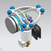
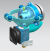
CycloidalExtruderDrive-History
This page conserves the development-history of the Cycloidal Extruder Drive.
Contents
Build v0.1
Objective
Quickly check general feasibility using some existing components:
- StepperOnline Nema 8 Bipolar 0.6A 4Ncm(5.7oz.in) mini stepper motor 8HS15-0604S
- MK8 Drive Gear
- E3D v6 HotEnd - 3mm Direct (12v)
Design
- Gearbox ratio: Some simple engineering calculations based on required feed-forces for 3mm filament and comparisons with existing extruder solutions propose for the 4Ncm stepper a gearbox ratio of approx. 20:1. Having an existing CAD model of a small cycloidal gearbox with a ratio of 36:1, this one was simply adopted.
- STEP-files of the assembly with detailed components, simplified geometry for the core parts (for simplifying mods) and some tools/jigs which help you to assemble this thing: Media:CycloExtruder v01.zip
BOM
- Printed parts
- 1 x StepperOnline Nema 8 Bipolar 0.6A 4Ncm(5.7oz.in) mini stepper motor 8HS15-0604S
- 1 x MK8 Drive Gear
- 1 x E3D v6 HotEnd - 3mm Direct (12v)
- 3 x MR105-ZZ (5x10x4mm) Ball Bearings
- 2 x MR128-ZZ (8x12x3.5mm) Ball Bearings
- 1 x 5mm Stainless Steel Precision Shaft (or a 5mm aluminium shaft from your local hardware store - make sure you go shopping with your caliper: 4.97..4.99mm is sufficient if you are on a hurry)
- 12 x DIN6325 2x10 Steel Dowel Pins
- 4 x DIN912 M2x4 Hex Socket Head Cap Screws (for fixing the stepper)
- 2 x Springs
- Various DIN912 M3 Hex Socket Head Cap Screws
Make & Assemble (not easy...)
- Print the parts: PLA, 2 perimeters, 100% infill, layer height 0.1mm, go slowly for the gears (15mm/sec or less)
- Tune the excenter's bore to make it go gently (!) over the motor shaft and you can remove it gently again (this is a design weakness...)
- Tune the excenter so you can assemble the bearings smoothly
- Press fit the bearings into the excenter gears, push them over the excenter
- Bolt the ring gear with the M2 screws to the stepper
- Mount the excenter/excenter gears over the motor shaft as follows:
- Make the D-shaft look to the left side
- Align the marking dot of the lower gear exactly to the right side
- Align the marking dot of the upper gear exactly to the left side
- Make sure this position is kept, while the excenter gears enter the ring gear
- Press fit the 5mm shaft into the output carrier (using the shaft-mask tool for perpendicular assembly)
- Press fit the 12 2mm dowel pins into the output carrier (the pin-mask tool and the pin-support-ring tool will help you)
- Assemble all the rest
Test & Validate
- Attached to an Azteeg X5, v1.1
- Motor current: 0.55A, 32 microsteps, 10500 steps/mm
- Retract: 0.5mm, 5mm/sec
- Speed: up to 80mm/sec, 0.4mm nozzle, 0.2mm layer height
- Did some very basic tests (10x10x5 blocks, Dia30 cylinders), in summary 1 hour printing
Results
- It prints
- No lost steps while extruding and retracting
- Some waivy surface appearance (compared to Bowden setup), probably related to poor tolerances
- Motor temperature: reasonable warm
- No specific noise
- No signs of gear wear after tear down - some normal surface flattening, running without grease
- Works basically - v0.1 objectives met
Todo
- Rethink the assembly process - it's a real pain
- Switch to a more effective 14HR05-0504S stepper recommended by Chri and others
- Evaluate tolerance stackup
- Switch to a hypocycloidal profile - build v0.1 uses arcs
- A lot more...
Build v0.2
Objective
- Gain further weight-saving by using the more effective 14HR05-0504S stepper
- Redesign gearbox for this motor and include some minor improvements
- Keep as many v0.1 components as possible
Design
- From the motor characteristics, a gearbox ratio 12:1 was calculated. However to keep the v0.1 output hub, a ratio of 16:1 is implemented
- No of teeth: 16, eccentricity: 0.8mm, radius: 17mm, roller radius: 1.5mm
- Tooth clearance tightened from 0.2mm (v0.1) to 0.1mm, aiming for less waviness while keeping printability with FDM machines
- STEP-files of the assembly with detailed components and simplified geometry for the core parts (for simplifying mods): Media:CycloExtruder v02.zip
BOM
- Printed parts
- 1 x StepperOnline Nema 14 .9deg Thin Stepper Motor 12.5mm 0.5A 7Ncm(10oz.in) 14HR05-0504S (50g)
- Same stuff as v0.1
Make & Assemble
- Basicaly like v0.1 - printing and assembly simpler due to larger features and aligning of some of the components' endfaces
- Hint: Cleanup the gears for running smoothly before assembly - remove any blobs and strings carefully
Test & Validate
- Attached to an Azteeg X5, v1.1
- Motor current: 0.45A, 32 microsteps, 10200 steps/mm
- Retract: 0.5mm, 5mm/sec
- Speed: up to 80mm/sec, 0.4mm nozzle, 0.2mm layer height
- Testing: 10x10x5 blocks, Dia30 cylinders, some larger parts, in summary 4 hours printing
Results
- Works basically
- No lost steps while extruding and retracting
- Started to slowly loose steps after 1 hour when printing a larger object - made further tests fail
- Less waivy surface appearance than v0.1, but still worse than Bowden setup
- Motor temperature: approx. 70°C (finger sensor...)
- No specific noise
- After disassembly:
- Excenter and excenter gears lost their press fit with the bearings, probably due to motor-heat induced material creep. This causes locking of the gears and loss of steps
- Some normal surface flattening, small amounts of worn-out particles - seems to be protruded material from the print being removed while in operation
- Weight (drive system + E3D v6 HotEnd): 138g
- v0.2 objectives met
Todo
- Make this thing more robust by using higher temperature resistant material
- Squeeze down packaging
- Try to further tighten tolerances
- Review various issues from poor design
Build v0.3
Objective (see development history)
- Improve heat resistance - previous build failed due to material creep
- Tighten tolerance stackup for better extrusion rate precision
- Squeeze packaging
Design (see development history)
- To shorten the tolerance stackup, an additional bearing now directly centers the output shaft with the motor shaft
- Tooth clearance reduced from 0.1mm (v0.2) to 0.05mm, aiming for less waviness while keeping printability with FDM machines
- Cleaned a bug in tooth shape formula of v0.1
- Based on v0.2 results, gearbox ratio is changed to 12:1 -> no of teeth: 12, eccentricity: 1.0mm, radius: 18mm, roller radius: 2.0mm
- Some exhaust air from the hotend is directed to the stepper motor for cooling
- STEP-files of the assembly with detailed components and simplified geometry for the core parts (for simplifying mods): Media:CycloExtruder_v03.zip
- STL-files: Media:CycloExtruder_v03_stl.zip
BOM
- Printed parts from some more heat resistant material than PLA (like ABS/PETG/..., I use ColorFabb's ngen)
- 1 x StepperOnline Nema 14 .9deg Thin Stepper Motor 12.5mm 0.5A 7Ncm(10oz.in) 14HR05-0504S (50g)
- 1 x MK8 Drive Gear
- 1 x E3D v6 HotEnd - 3mm Direct (12v)
- 3 x MR105-ZZ (5x10x4mm) Ball Bearings
- 2 x MR128-ZZ (8x12x3.5mm) Ball Bearings
- 1 x MR85-ZZ (5x8x2.5mm) Ball Bearing
- 1 x 5mm Stainless Steel Precision Shaft (or a 5mm aluminium shaft from your local hardware store - make sure you go shopping with your caliper: 4.97..4.99mm is sufficient if you are on a hurry)
- 10 x DIN6325 2x10 Steel Dowel Pins
- 5 x DIN912 M2x8 Hex Socket Head Cap Screws
- 2 x DIN912 M3x8 Hex Socket Head Cap Screws
- 2 x DIN912 M3x16 Hex Socket Head Cap Screws
- 2 x Springs 0.8 x 4.7 x 15 (wire dia x outer dia x length)
- 2 x DIN912 M3x25 Hex Socket Head Cap Screws
- Ball Bearing Grease
Make & Assemble (not easy)
- Print the parts: 2 perimeters, 100% infill, layer height 0.1mm, use ABS/PETG, go slowly for the gears (15mm/sec or less)
- Cleanup the gears for running smoothly before assembly - remove any blobs and strings carefully - take your time for precision later on
- Tune the excenter's bore to make it go gently (!) over the motor shaft and remove it gently again (this is still a design weakness...)
- Tune the excenter so you can assemble the MR128-ZZ bearings
- Press fit the MR128-ZZ bearings into the excenter gears, push them over the excenter
- Bolt the ring gear to the stepper motor
- Mount the excenter/excenter gears over the motor shaft as follows:
- Make the flat side of the D-shaft look to the right side
- Align the marking dot of the lower gear exactly to the left side
- Align the marking dot of the upper gear exactly to the right side
- Make sure this position is kept, while the excenter and the excenter gears enter the ring gear
- Push the excenter onto the shaft until the motor shaft is max. 1.2mm above the excenter's endface (when pushing further, the excenter will start to touch the stepper motor inside the gearbox...)
- Add grease to the gears and to the holes for the pins
- Press fit the 5mm shaft into the output carrier (using the shaft-mask tool for perpendicular assembly)
- Press fit the 10 2mm dowel pins into the output carrier (the pin-mask tool and the pin-support-ring tool will help you)
- Assemble all the rest
Test & Validate
- Attached to an Azteeg X5, v1.1
- Motor current: 0.45A, 32 microsteps, 7000 E-Steps (400 steps/rev * 32 microsteps / 21 mm/rev * i=12:1 -> 7.314 steps/mm)
- Retract: 0.5mm, 5mm/sec
- Speed: up to 80mm/sec, 0.4mm nozzle, 0.2mm layer height, material: PLA, temperature: 210°C
- Testing: 10x10x5 blocks, Dia30 cylinders, some larger parts 2-3 hours each, in summary 12 hours printing
Results
- Works - has survived successfully test prints
- No lost steps while extruding and retracting during prints
- Motor temperature: approx. 50°C - the air shield seems to help
- Less waivy surface appearance than v0.2, but still not matching my Bowden setup
- No specific noise
- Loosing steps when manually extruding 5mm from the controller
- Output shaft started to slip in output hub - fixed by adding superglue to the press fit
- After disassembly:
- Grease without any worn-out particles, looks like new
- No wear on teeth, some surface flattening on pin holes but not wear
- Bearings still press fitted on the excenter and inside gears
- The excenter is hard to print, to prepare and to assemble
- v0.3 objectives met
Todo
- Go back to 16:1-ratio for robustness against loosing steps
- Improve fit of centering bearing on motor shaft: Gain axial space by using bearings without shields
- Review various smaller issues
Links
- The home page of the Cycloidal Extruder Drive
- Wikipedia: Cycloidal drive
- Design of a Planetary-Cyclo-Drive Speed Reducer Cycloid Stage, Geometry, Element Analyses
- Building a Cycloidal Drive with SOLIDWORKS
- Generate DXFs of hypocycloid cams for cycloid drives
- RepRap Forum: This engineer claims 100 grams direct extruder
- Build v0.1: Google Album
- Build v0.2: Google Album
- Build v0.3: Google Album


