Extruder Controller Board v1.2
Contents
Extruder Controller Board - v1.2
Prerequisites
This board is a modified Universal Controller Board v1.2. as shown on the right. Build that first, then follow the steps here.
Make it!
Add the following components to the Universal Controller Board:
| Component | Value | Quantity | What is it | Mouser # |
| R1 | 10K ohm | 1 | Resistor | 291-10K-RC |
| R3 | 180 ohm | 1 | Resistor | 291-180-RC |
| R5 | 220 ohm | 1 | Resistor | 291-220-RC |
| R12 | 560 ohm | 1 | Resistor | 291-560-RC |
| C3 | 10nF (See note below) |
1 | Ceramic Capacitor | 594-K103M15X7RF53H5 |
| C5, C6 | 0.1uF | 2 | Ceramic Capacitors | 647-UVR2A0R1MDD |
| D10 | LED | 1 | heater-on indicator | |
| Q1 | TIP110 | 3 | Darlington can use TIP120 | 511-TIP110 |
| P2 | 2 pin | 1 | connector to the thermistor | |
| P4 | 2 pin | 1 | connector to the heater |
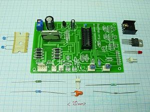
On the right, we have a picture of the additional bits listed above clustered around a Universal board. They happen to be listed pretty much in order of height above board, so that's not a bad order to install them in.
Note: The value of C3 (nominally 10nF = 0.01uF) depends upon the thermistor that you will use to measure the temperature of the extruder head. The standard thermistor that RepRap uses is a miniature glass-bead type, which is available from RS, part number 484-0149 . This is a 10K thermistor (at 25oC) with a beta value of 3480K and a 0oC resistance of 29K. But the design is capable of dealing with a variety of different thermistors - just get one that will go up to about 200oC and use the calculator at this link to work out the value of C3. The best value of C3 for the standard thermistor is 0.01uF.
When you know C3 run the RepRap Java control software and select Preferences from the File menu. Select the extruder tab and set the capacitor's value:
Extruder0_Capacitor(F) 0.0000001
that line is for 0.1uF; enter whatever value you choose. Click on OK.
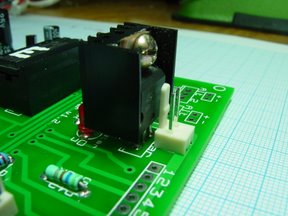
<div class="thumb tright"></div>The transistor Q1 - either a TIP110 or the beefier TIP120 - has to go in the right way round. Yes, we got it too close to the heater connector and it's very close to the heater LED - sorry about that; it's our first bulk order board and we also got the transistors too close together; fortunately only one is needed for the standard extruder. Try soldering Q1 in on slightly longer leads than normal, and use a small LED to make sure it all fits together.
As both the cooling fan and the extrude motor are reasonably low-current devices you don't need to add a heatsink to the L298N (U2). But you do need one on the transistor, which you attach after soldering it in place as shown in the photo on the right - do make sure you get it in the right way round! Remember to put a bit of silicone grease or a silicone heat transfer pad (which is much less messy) between the transistor and the heatsink. Do not let the heatsink touch any other components or wires. Feel free to use a bigger one if you can fit it.
Program a PIC16F648 with the file in ~your-id/workspace/firmware/devices/extruder_0_/extruder_0_.hex and place it in the socket.
Test It
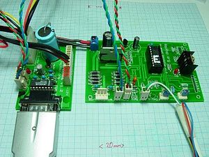
<div class="thumb tright"></div>This picture shows the board complete and connected ready for testing. There are an additional couple of useful test components plugged in either side of the serial data wires.
If you haven't got an extruder assembled yet, it is useful to solder a couple of connectors onto the thermistor you will use so you can plug it straight into the board (the connector sporting the green and white pair in the picture). The thermistor is not wasted - it will need much shorter leads in the actual extruder, so you can just cut the connectors off then. The extruder board will not work without a thermistor attached. If you have no real thermistor yet, use an ordinary 10K resistor.
Connect an RS232 cable between your computer and the Comms/power board. Connect transmit (T) on the Comms board to receive (R) on your new board, and receive (R) on the Comms board to transmit (T) on your new board. You can use the same wiring and configuration as the final testing phase of the Universal PCB.
Open the Eclipse Java development program. Open the Reprap project, and walk down the tree: src -> org.reprap. Right-mouse click on main.java and go down to Run as... -> Java Application.
Select Preferences from the File menu and set the port to the one your RS232 cable is connected to.
Click on the Axes tab and select Cartesian as the geometry. (The default is Null Cartesian, which is a dummy RepRap machine inside the software for testing purposes.) Cartesian is an honest-to-goodness real RepRap, such as the one taking shape on the end of your RS232 cable...
Click on OK in the Preferences box.
Turn on the power.
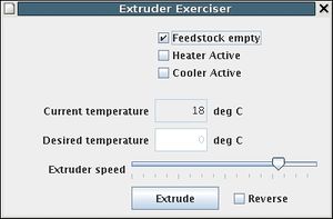
Now, from the Tools menu select Extruder exerciser. This should open a window that looks like this:
The Feedstock Empty box will be checked if you have a jumper on K1, as in the picture.
Hold the thermistor between your thumb and finger. Your body heat should cause the Current temperature to rise (this will take a few seconds).
Check the Heater Active box. Enter a Desired temperature of about 30oC above the Current temperature and press "Enter". The heater LED (at the right in the picture above) should flash. This flashing is the heater coming on and off using pulse-width modulation to set its power. If it doesn't come on, you may have either the LED or the transistor in the wrong way round.
Close the window and turn everything off.
Final steps
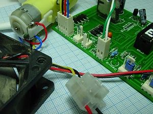
<div class="thumb tright"></div>Ensure you have a heatsink attached to the power transistor, connect up the extruder heater and extruder thermistor. Connect an LED diagnostic tool described here - the device on the fan and extrude motor output (left of the serial data connectors). You can use a real motor and fan if you wish; in this image, the red & blue wires connect to the extruder motor, black (the ground) and yellow (12V) to the fan:
When you first turn the heating element on, start with a low temperature (40-50C). Check it is heating as expected and then incrementally check at higher temperatures.
Check the Cooler Active box. The other back-to-back LED should light. This is the cooling fan coming on.
Click on the Extrude button. One of the four back-to-back LEDs should light. This is the extrude motor coming on.
Switch both off by clicking both again.
Congratulations! You now have a fully working and tested extruder controller.
If you plan on having two extruders on your RepRap, make another one. Then you can proceed to making the extruder mechanics.
Variations (for advanced developers only)
---
Alternate power transistors
A BD681 is a suitable alternate part to the TIP110/TIP120 if more readily available. Note however that the pinouts are in the reverse order, so you must either wire the board differently or simply face it in the opposite direction - whence its heatsink will collide with the heater's 2-pin termial. The BD681 and TIP120 are rated at 4A continuous whereas the TIP110 is only rated at 2A continuous. This means with the BD681 or TIP120 you can heat more quickly and reach a higher temperature -- choose your heating element to suit.
Heating element
The heating element is made from nichrome wire. The correct length must be used to prevent drawing too much current for the power supply to handle or too little current to sufficiently heat the material.
First you must select a suitable power output, in general this should be as high as you can afford in your total energy budget. So for example, if your power supply is rated for 12V@10A and the motors and other parts use 6A at peak, then you have 4A to play with for the heater. Ensure you don't choose a current that is too high for the switching transistor deal with. In the schematic above a TIP-110 is used which can handle 2A continuously and 4A for short pulses. For safety, we will restrict ourselves to 2A.
By Ohm's law, V=IR or equivalently R=V/I. So R = 12V / 2A = 6Ω (ohms). So the desired resistance for the nichrome wire is 6Ω.
If you check the specifications for your nichrome wire, it will have a value in ohms/meter at a given temperature. You want the value at around your anticipated working temperature. The resistance drops as the temperature increases. The dropping resistance raises the temperature, which in turn drops the resistance further. Luckily this doesn't go on forever but it leads to fairly inaccurate power consumption if you don't have it right.
Say your wire is rated at 13.4Ω/m at 208C (as mine is). Then to get the desired 6Ω, you need 6Ω / 13.4Ω/m = 0.447m or around 45 centimetres.
This should be connected with heavy gauge wire and wound around the object to heat (which much be non-conductive or electrically insulated).
Similarly, if you wish to drive 3A, which you can quite happily do with a BD681, you would use 30cm of wire.
If you decide to drive a higher current than your transistor is rated for, remember not to set the output power to full or you will probably damage the transistor (and possibly yourself). Not recommended
How to estimate the resistance at your working temperature if your wire specs only have it for a different temperature
Firmware
See the main Extruder Controller page for firmware.
A snapshot of the latest source is available for viewing
Troubleshooting
If you experience trouble, please share the problems (and resolutions) with us.
Testing The Unit
Attaching the thermistor is currently essential. The extruder motor will not turn until the thermistor is connected.
Testing is accomplished with the "poke" command from the SNAP firmware/tools directory. First, test your communications link as per the serial controller board section.I used device /dev/ttyUSB0 - a serial USB adaptor. The -v option gives debugging, which tells you if the device is sending an ACK back or not. The device number for the first extruder is 8; further extruders may be added later.
Extruder Motor
To get the motor to go forward, start off gently and then increase the power initially, send the "extrude" command to extrude at rate 50:
and this turns it off:
If that doesn't make the motor move, and the circuit is not warming up, then increase the value from 50 to 200 and try again.
Testing The Thermistor
The command:
Should return 3 numbers on the end of the output that are related to the temperature of the thermistor. It's quite sensitive and you should be able to make the value change by holding the thermistor between your fingers. When you let go, it should return to its previous value.
Testing The Heater
Now to test the heater element. Ensure that your cables are up to carrying the amperage that your element will draw - add a set of screw terminals to allow a heavier duty supply if necessary. The following will set the heater element to 88:
If you have a K/T thermocouple with a relatively fine end, this can be inserted into the extruder nozzle to give accurate temperature readings when testing out new materials etc.
[We also need to know when the element has reached working temp.]
Technical
Pinouts
When programmed into a PIC16F648, or PIC16F648A (default), the pinouts are:
- RA2/AN2/Vref ...... Cooler output
- RA3/AN3/Cmp1 ......
- RA4/T0CK1/Cmp2 .... Reserved for LED output
- RA5/MCLR/Vpp ......
- Vss ............... Ground
- RB0/INT ........... Heater PWM output
- RB1/RX/DT ......... RX
- RB2/TX/CK ......... TX
- RB3/CCP1........... Extruder motor PWM output
- RB4/PGM ........... Forward signal
- RB5 ............... Reverse signal
- RB6/T1OSO/T1CK1/PGC Feedstock empty sensor
- RB7/T1OS1/PGD ..... Motor position opto-interrupter input
- Vdd ............... +5V
- RA6/OSC2/CLKOUT ... Temperature slope A/D test charge
- RA7/OSC1/CLKIN .... Temperature slope A/D thermistor charge
- RA0/AN0 ........... -
- RA1/AN1 ........... Temperature slope A/D input


