Adrian's Geared Extruder
|
English • العربية • български • català • čeština • Deutsch • Ελληνικά • español • فارسی • français • hrvatski • magyar • italiano • română • 日本語 • 한국어 • lietuvių • Nederlands • norsk • polski • português • русский • Türkçe • українська • 中文(中国大陆) • 中文(台灣) • עברית • azərbaycanca • |
Mechanical: Overview | Mendel solid model files | Procurement | Preparation of materials | Assembly notes | Extruder | X-axis | Z-axis | Y-axis | Circuit boards | Frame | Squaring the axes
Release status: Working
| Description | Geared Nema17 Extruder Driver
|
| License | GPL
|
| Author | |
| Contributors | |
| Based-on | |
| Categories | |
| CAD Models | |
| External Link |
Contents
Introduction
This page describes the standard extruder for RepRap Mendel. Equally, lots of people have success with Wade's Geared Extruder too which you may care to take a look at.
This extruder is designed to work with a supply of 3mm diameter plastic feedstock. If you want to use 1.75mm diameter plastic, see this extruder instead.
I wanted to design a single extruder driver that could
- Be bolted to the X carriage of Mendel and run as a normal extruder,
- Be mounted somewhere at the side and drive a Bowden extruder (as invented by eD and developed by Erik), and
- Be mounted somewhere at the side and drive a Bowden paste extruder, as outlined here.
Features
- 59:11 gear ratio means that the motor runs on very low current; prime numbers of teeth mean even wear
- No hobbing or knurling needed to make the filament driver
- Torque transmitted using a wing nut, giving low stress on reprapped gears
- Uses the same 624 bearings as the rest of RepRap Mendel
- Designed to work at higher extrude speeds than the old Mendel extruder, giving shorter build times.
What you need
This describes what you need to build an extruder to mount on Mendel. The Bowden variations will be added below when they have been tested.
See this page for a better nozzle design for this device. You may well want to make that rather than the one described below.
The design files (AoI, STLs, and the complete RFO for immediate reprapping) are in the repository here.
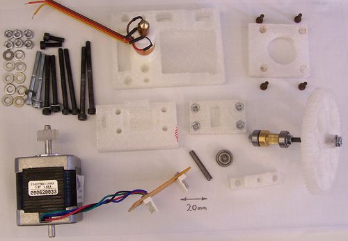
This picture shows all the parts (some partly assembled) except for the two M4x20 screws that attach the extruder to Mendel's X carriage.
| Description | Quantity |
| base.stl | 1 |
| drive-gear.stl | 1 |
| driven-gear.stl | 1 |
| driven-holder.stl | 1 |
| filament-guide.stl | 1 |
| idler-holder.stl | 1 |
| motor-holder.stl | 1 |
| M3x10 | 4 |
| M3 set screw 10mm | 1 |
| M4x12 | 2 |
| M4x20 | 2 |
| M4x45 | 6 |
| M4x55 | 2 |
| M3 nut | 1 |
| M4 nuts | 13 |
| M4 wing nut | 1 |
| M4 washers | 21 |
| 624 bearings | 3 |
| NEMA17 stepper | 1 |
| M4 threaded rod | 70mm |
| 4mm diameter rod | 37mm |
| M4 insert | 1 |
| Strip-board | 50mmx25mm |
| 4-way pin headers | 2 |
| 4-way ribbon cable | 130mm |
| 16mm dia PTFE | 50mm |
| M6 threaded brass | 36mm |
| Thermistor | 1 |
| Kapton tape | 200mm |
| Nichrome wire | 6 ohms |
| Araldite rapid | About 5 ml |
Here is a complete list of all the parts and materials.
The M4 Insert is what drives the filament and is the heart of the device. It is available from here, UK or here for Europe or these guys ship worldwide or these guys (mixshop.ca) ship worldwide too. It has an internal M4 thread and a locking grub screw. This means that it is very easy to mount on the 70mm length of M4 threaded rod, but that - once it is tightened up - it never slips. It is made from brass, and so it will eventually wear, even though it is only bearing on plastic. I find that, printing with PLA, one of these lasts for about 50 Kg of printing, so it's worth buying a few spares (compared to the cost of the plastic, this is trivial, of course). If you're having difficulties sourcing them, or simply need a quick alternative while waiting for the proper piece to arrive, then some people have had success using two dremeled M4 nylocs as a replacement.
The stepper motor is a NEMA 17 motor with a double shaft (front and back). The RepRap stepper motors page is here. I used the one from Zapp Automation, which works fine.
The 4mm diameter rod can be an old M4 bolt shaft (the unthreaded bit) hacksawed off. Clean the ends with a file.
Putting it together
The connector
The two 4-pin headers are used for the four stepper wires, and for the two heater and two thermistor wires.
Use the driven holder part as a drilling jig to drill two 4mm holes near to the bottom edge of the stripboard. Solder the two 4-pin headers near the top and towards either end. Split the tracks down the middle to isolate the two connectors from each other.
If you wish you can solder a 1K resistor in series with a LED in parallel with the heater next to the heater and thermistor connector. That will give a visual indication of when the heater is on. Make sure you get the polarity right if you do this - conventional current (+ to -) flows in the direction of the arrow on the LED symbol.
The nozzle
Note: There is now a much better nozzle design that you can find here.
Note: some people have had trouble making extruders (like this one) from PTFE - they find it distorts under load. Others (including me) have no problems. This implies that there is more than one grade or composition (possibly with more or less polymerization) out there. We are investigating to find an authoritative answer. Meanwhile, the PTFE I used was this one, which worked for me...
Start by building the extruder nozzle. This is exactly the same as the one on the old Mendel extruder here except that the PTFE is longer at 50mm than the 35mm used for the previous design. I also cut the M6 thread slightly longer (18 mm) than the 15mm used for the previous design, and made a correspondingly longer brass nozzle.
The reasons for these changes (which may not actually be necessary) were conservative: I wanted to be really sure that the Araldite join between the PTFE and the base of the device would stay very cool and so not soften. And I wanted to make sure that the brass nozzle would not break lose, even under higher forces than the original extruder is capable of generating. One of the main reasons for designing this device - as mentioned above - is to increase the speed of extrusion. Doing that will obviously generate higher thermal and mechanical stresses, and so I thought it best to be prepared.
The longer nozzle does mean that you will have to put a longer Z-axis opto-flag on your Mendel to use this.
The gear drive
The large 55-tooth gear is the one that drives the filament. It connects to the 70mm M4 threaded rod using a wing nut, which spreads the torque load on it and thus reduces the stress that the plastic is subjected to.
Start by offering up the wing nut to the slots in the large gear on the opposite side to the projecting boss. Some wing nuts fit immediately. Unfortunately there does not seem to be a completely standard shape for wing nuts, so you may have to file down the inner shoulders of yours to fit, as shown here. The gear should sit flat on top of the inner part of the nut.
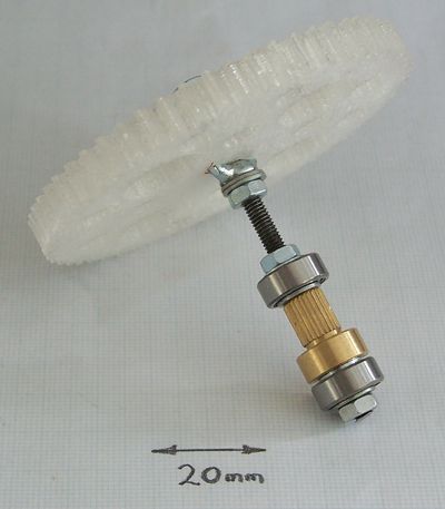
This shows the assembled filament drive. The sequence from the bottom is:
| M4 nut | M4 washer | 624 bearing | M4 washer | M4 Insert | M4 washer | 624 bearing | M4 washer | M4 nut | GAP | M4 nut | M4 wing nut | gear | M4 washer | M4 nut |
There are a couple of extra washers in the picture between the wing nut and the nut that locks it - these are not needed. The final M4 washer and nut are invisible behind the gear.
Get everything in the right sequence and hand-tighten it all. Don't use spanners and force yet.
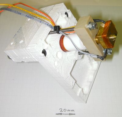
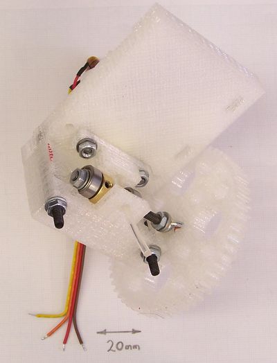
This shows the assembly fitted in its slots in the extruder. Use a short length of filament down through the device to hold it in place while you build the rest.
The stepper drive
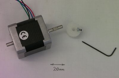
The gear on the stepper motor is held with an M3 set screw. I use one 10mm long. Insert an M3 nut into the cavity in the gear, then put the screw in. If this is a bit tight and rubs against the body of the gear, don't worry. That's actually good as it helps hold the screw in place.
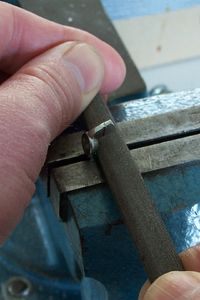
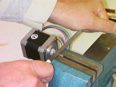
If your motor's shaft has a ready-made flat on it, simply tighten the set-screw against that. If not, put the shaft in a vice and file a small flat with a narrow file. Note the Blu-tack temporarily stuffed into the motor's bearing. This prevents any iron filings getting in. Get the flat in the right place. The gear needs to end up so that its face nearest the motor just clears the M4 screw that runs through the motor's reprapped mounting plate.
Use the four M3x10 screws to attach the motor and gear to its reprapped mounting plate, and then attach that to the base using two M4x55 screws in the slots provided. Those slots are to allow you to move the motor towards or away from the big gear so that you can get the teeth meshing well.
Adjust the nuts and wing nut holding the big gear that you left hand-tight on the driven gear assembly so that the two gears line up. Take the driven gear assembly out (remove the short length of filament you put in to free it).
Tighten all the nuts on the driven gear assembly pretty hard with a couple of spanners. Don't go over the top and strip the threads, though. Double check that everything lines up, then finally tighten the grub screw in the M4 Insert. This will bite into the 70mm M4 thread; you will be able to undo it again if absolutely necessary, but you don't want to have to do that too often (or at all). Fit the assembly back in and again retain it with the short length of filament.
Take the stepper and its mounting off.
Put four M4 nuts in the holes for them in the reprapped idler holder. Use an M4 screw with a washer under its head to drag them into their holes if they are a bit tight.
Put the final 624 bearing on the 4mm-diameter rod and put an M4 washer either side of it. Place it in the declavity in the idler holder.
Drop four M4 screws with washers down the holes in the driven holder, using the top two to retain the stripboard.
Offer the idler holder up underneath and screw the screws finger tight compressing the filament between the M4 insert and the idler bearing. Look down on the top of the device and adjust the screws to get the idler holder parallel to the driven holder.
Put the motor back on and adjust it so that the gears engage. Make sure that the large gear can turn freely through a complete revolution whilst neither disengaging nor running the gears too close together.
Put a small amount of silicone grease on the gears to lubricate them.
The finished device
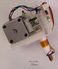
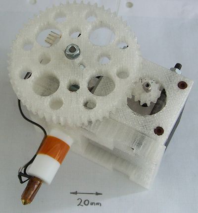
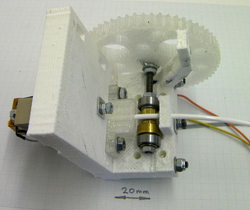
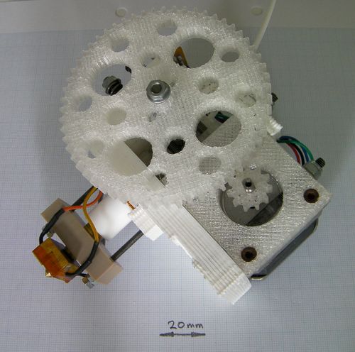
Front view.
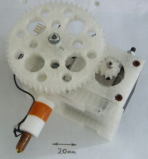
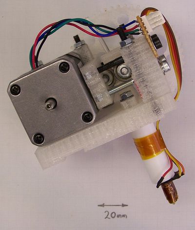
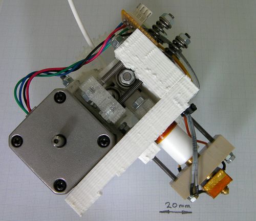
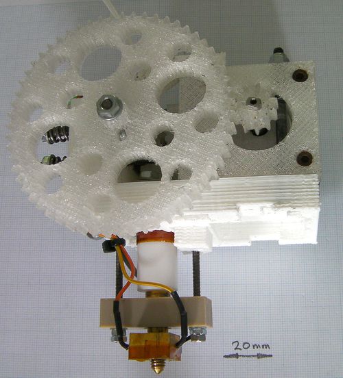
Back view.
The number of steps per mm-of-extrusion in the firmware needs to be changed from that of the standard extruder, of course. Firmware details are here. I used a figure of 1.8 steps per mm, with a half-stepped 200 steps/rev motor.
Video of it working
Variations on this design
This is the place to add variations and improvements to this design.
Spring loading
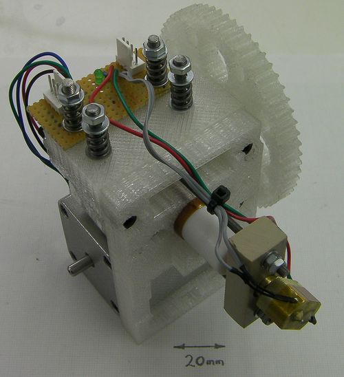
This is a better, more reliable and more compliant arrangement for forcing the idler bearing and the drive insert together. For this variation you need 4 fewer M4x45 cap bolts as required in the original BOM, (furthermore the two remaining M4x45 bolts can be longer if you like, meaning you can just do away with all six M4x45 bolts add two extra M4x55 bolts to the BOM. Then you have fewer different bolt sizes in the BOM to worry about) . Cut four lengths of M4 threaded rod 62 mm long. On each, tighten a pair of lock-nuts on one end. Try to align the nut flats, but don't strip the threads. Alternatively instead of the threaded rods and nuts you can use some M4x70 hex bolts, as the heads of these bolts are the same size as M4 nuts.
Place the lock-nut ends in the four hexagonal holes in the idler holder. Once assembled, on the other end put a stack: washer, spring, washer, nut.
The springs I used were Springmaster's D12100, but any springs with roughly these characteristics will do. Springmasters have a minimum order of £15 which is ideal as it will get you 8 of the D12100 springs, that's 4 to use and 4 as spare.
Don't over-tighten the springs. With the ones I used, you do them up untill they just touch, then add one and a half turns. Tighten them diagonally; that is do them up in an order like bottom left, top right, top left, bottom right. If you find yourself having to do them up significantly tighter, it's a sign that something else is wrong with the extruder like a partially-blocked nozzle or the drive wearing (see above).
This device give a more-or-less constant pinch force on the filament as it passes through the extruder, even if the filament has slight changes in diameter.
Load spreading
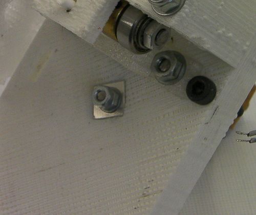
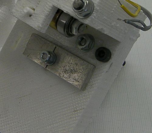
After a lot of use (printing about 20 Mendels) I discovered that the small aluminium plate that spreads the load from the M3 nozzle retainer by the stepper motor had worked its way about 1mm into the plastic of the extruder base plate (see above).
The solution is to increase the size of the plate, of course. I replaced it with a piece 40mm x 12mm with a 3mm hole drilled 17mm from one end and 8mm from one long edge.
See Also Extruder Driver Variations
