PIC in-circuit programming
PIC in-circuit programming (includes In-circuit serial programming; ICSP): The RepRap controller boards have been designed to allow you to program the PIC chips plugged into them (or soldered in, if you're feeling brave). You will need to make up a small connector to go between your PIC programmer and the boards, and also you will need to solder an extra two-pin connector to each board. This page tells you how.
The connector
This will probably not work with a PIC programmer that derives its programming voltages from the computer's RS232 line. That's a fairly dodgy practice at the best of times, as the voltage regulation and current are not well controlled by some computers. Use a programmer that gets wholesome electrons organically-grown from an honest-to-goodness power supply.
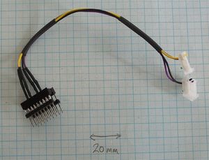
You will need an eighteen-pin header to plug into your programmer where the PIC would normally go. We made one by soldering two nine-pin lengths of pin strip to an eighteen-pin socket.
You will also need a three-pin and a two-pin socket. The three-pin socket will plug into the RepRap Universal Controller board where the Max/Empty opto-switch normally goes. The two-pin socket will plug into two new pins soldered onto the board (see below at A).
Connect four short wires as follows:
- Header pin 4 -> 3-pin middle
- Header pin 5 -> 3-pin left (when the writing on the RepRap PCB is the right way up)
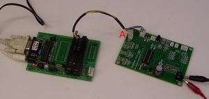
- Header pin 12 -> 2-pin into connection 4 on the left edge of the RepRap PCB (A in the picture below)
- Header pin 13 -> 2-pin into connection 3 on the left edge of the RepRap PCB (A in the picture below)
Don't be tempted to make a long cable up so you can drape it round your RepRap machine when programming in-circuit. Your cable is mediating wide-band RF-signal. This would allow you to leave the programmer on the bench, but it won't be reliable. Better to hang the programmer on the machine with a bit of string...
Programming
Solder a two-pin plug into the connections numbered 3 and 4 on the left of the Universal Controller board at A in the picture.
If you're programming the PIC in a board in a RepRap machine, unplug all connections from the board except power.
Plug the header into your programmer (on the left of this picture). Plug the three-pin connector onto the Max/Empty board pins. Plug the two-pin connector onto the plug you just soldered.
Power up your programmer. Power up your Universal Controller board from the Power and Communications Board.
You should find that the programmer reacts as if the PIC was plugged directly into it. You should be able to read the PIC, to verify it and to program it.
-- Main.AdrianBowyer & IanAdkins - 06 Feb 2008

