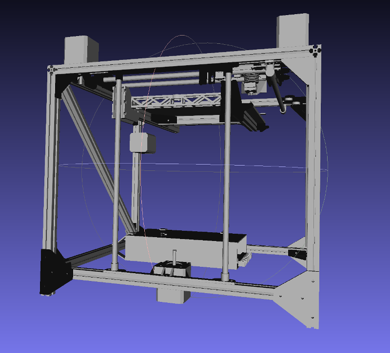
Mechanical Rigidity/Fusebox classic flawed cantilever printbed
Fusebox: inadequate 8mm rods, single lead screw, cantilevered bed with insufficient support
The Fusebox is a low-cost design that highlights a huge number of flaws with the average classic cantilevered printbed.
The flaws in this design are numerous:
- Firstly, the rods are only 8mm. With almost 250mm to the end of the printbed, a "lever" effect can create significant amounts of bend to adversely affect the quality of the print as weight accumulates on the printbed.
- Secondly, there is only a single lead screw with a distance between the rods of 140mm, spanned by a single piece of plastic only 20mm in height (and 130mm in length). This creates the possibility of a rotational moment about the Y-axis: one linear bearing can go up whilst the other can go down, wobbling the entire printbed in the process, by several millimetres. If a print is ever made off-centre on this design it will gradually push the printbed further down on that side and will no longer be straight!
- Thirdly, the 130x20mm horizontal piece between the rods and spanning that 140mm gap is simply not strong enough: it will bend under load.
- Fourthly: LM8LUU bearings, even at 45mm in length, are of insufficiently high quality machine tolerances to prevent rotation about the X-axis (drooping of the front of the printbed) and the Y-axis (wobbling printbed, side-to-side).
- Fiftly: the LM8LUU bearing holders are not sufficiently long - or strong - to be able to hold up the weight of the printbed itself: the plastic of the bearing holders will therefore bow under the weight, causing inaccurate printing.
This example therefore highlights a huge number of classic design mistakes with cantilevered printbeds that are sadly extremely common. To fix these issues, the following needs to be considered:
- Replacing the 8mm rods with at least 10mm (preferably 12mm) rods, or, better, going to linear rails attached firmly and properly to the aluminium frame, at least 20x20 in size. This ensures that there is no "bend" (flex).
- Use of an L-shaped piece of aluminium between the rods, and, if sticking to rods, using four blocks of high precision of the type which have four mounting points. The height of the L-shape should be at least 75mm so as to prevent rotation.
- Rigid (metal) triangular bracing struts on both sides, from the bottom of the L-shaped aluminium to the centre of the printbed.
- The L-shape of the aluminium plate has two effects: first it stops bending of the plate (without needing huge amounts of material) and second a hole may be drilled in the horizontal part so that the lead screw can be attached through it.
This analysis is completely independent of the additional problems caused by the use of plastic in the corners, 15x15mm extrusion, and the complete lack of rigidity of both the base and the top. These additional flaws will further exacerbate the other issues with the printbed support itself.
Good aspects of this design however are the belt layout, which is properly laid out (stacked belts) and contains right-angles only: no drooping or "crossing", and the carriage is a horizontal layout which reduces the effects of rotation caused by the use of linear bearings.
