Megatronics 3.0
| |
Warning This Page seems to be under development. Images and linked files are still a mixture of Megatronics 2.0 and 3.0 |
Release status: Working
| Description | Single board solution, Remix of Arduino mega and RAMPS
|
| License | |
| Author | |
| Contributors | |
| Based-on | |
| Categories | |
| CAD Models | |
| External Link |
Contents
Summary
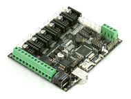
After using RAMPS for a long time I am still quite fond of it. There are some aspects of the board however that make it unusable for future electronics, which should be reliable and cheap. Also the wiring can we a bit fiddly. I have combined the Arduino MEGA and RAMPS boards into a single board solution. Only the stepper drivers are still modules for easy replacement.
Megatronics is based on many famous open-source products including: Arduino Mega 2560, RAMPS, SD Ramps. Therefor this product is an already proven design. It combines all major features of these board into a single board solution for more reliable 3D-printing.
Megatronics has a powerful Atmega2560 processor with 256 kB memory, running at 16Mhz. The board can be connected to a PC using a normal USB cable. It will register as FTDI FT232R device. The board is compatible with the Arduino Mega 2560 and will therefor be easily programmed from the Arduino IDE.
Configuring Arduino
The board is supplied with a Marlin firmware. Because of continued development and your specific needs, you may want to upload another firmware. You can use Arduino IDE to upload firmware to the Megatronics board. Under Linux select as board 'Arduino Mega 2560 or Mega ADK'. Under other operating systems the USB will not be reset correctly and you will need to adjust the boards.txt. This file is located in <Arduino directory>/hardware/arduino/boards.txt. Add the following text to the file:
megatronics.name=Megatronics
megatronics.upload.protocol=wiring
megatronics.upload.maximum_size=258048
megatronics.upload.speed=115200
megatronics.bootloader.low_fuses=0xFF
megatronics.bootloader.high_fuses=0xDA
megatronics.bootloader.extended_fuses=0xF5
megatronics.bootloader.path=stk500v2
megatronics.bootloader.file=stk500boot_v2_mega2560.hex
megatronics.bootloader.unlock_bits=0x3F
megatronics.bootloader.lock_bits=0x0F
megatronics.build.mcu=atmega2560
megatronics.build.f_cpu=16000000L
megatronics.build.core=arduino
megatronics.build.variant=mega
Restart Arduino IDE and select Megatronics as board. You should be able to upload correctly now. While uploading the blue LED is lit and the RX/TX LEDs will blink fast.
Testing the board
To test the functionality of the board, a test firmware is available. You can download it from the files section. This firmware will help you test the board. Disconnect everything except the USB cable to your computer. Upload the the test firmware to the board with Arduino, the blue debug LED should blink every second. By using the serial monitor in Arduino the board will provide an output like: T1 1023 T2 1023 T3 1023 TC1 700 TC2 700 These values represent the resistance measured from t1 to t3 and thermo couple 1 & 2. When you connect a thermistor to the pins, the corresponding value in the serial monitor should change to about 890.
By connecting the 12V lines, the MOSFETs should have power and their LEDs will blink in order. This verifies the MOSFETs and 12V power are OK.
Also the stepper motors should turn when connected, with the 12V lines and stepper drivers in place. They will turn a short time and switch direction.
These three tests will verify the basic functionality of the board.
Basic setup
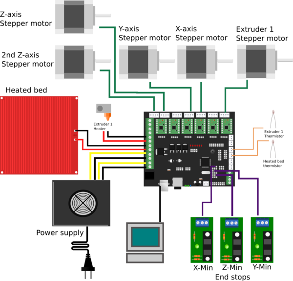
This paragraph will show you how to connect the board. This is just a basic example, your requirements may differ. There is a lot of community support available in the RepRap forums. By placing your questions there other users may benefit of the information too.
First connect your computer with a standard USB cable. The power LED should light up and the blue debug LED should blink once. The rxd and txd LEDs near the USB connector may blink fast for a short period.
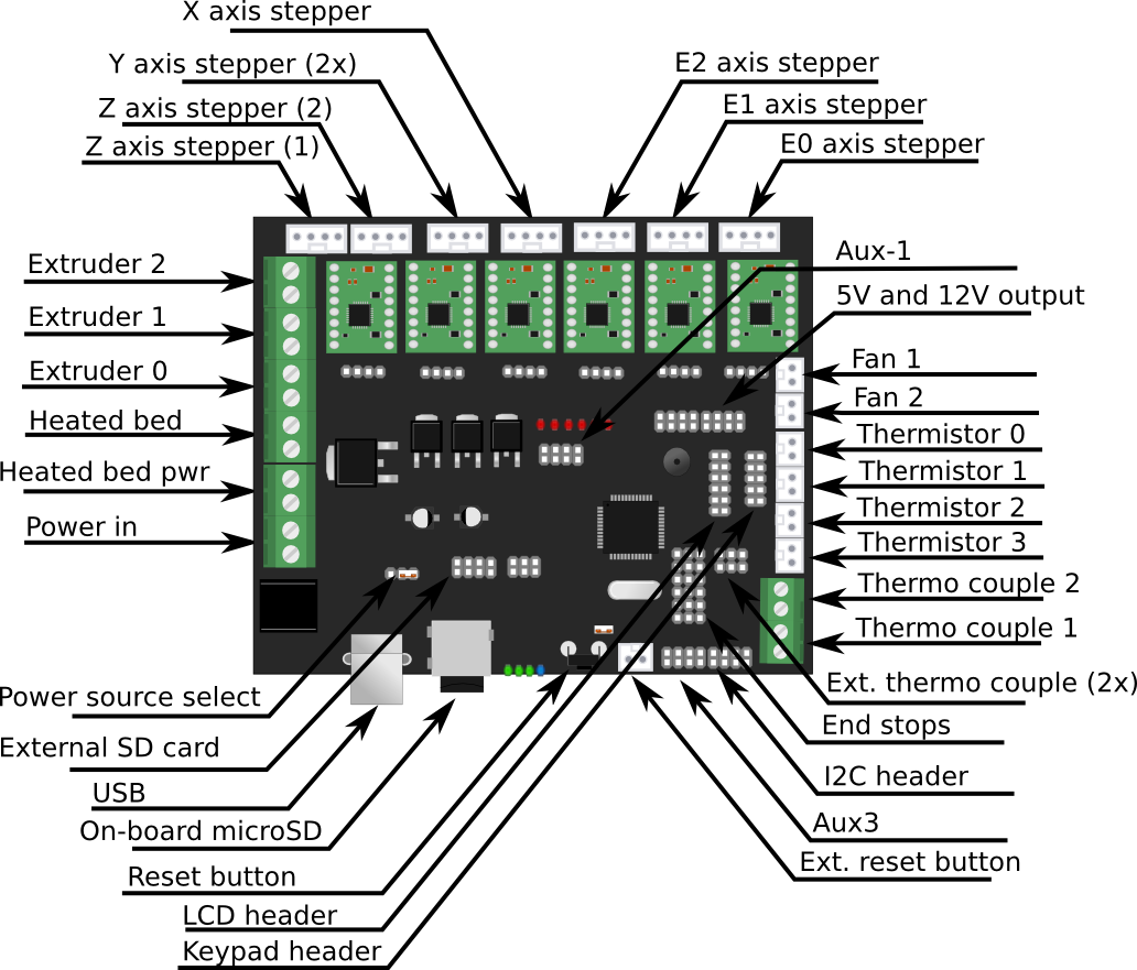
Put the stepper drivers in the slots, and connect the stepper motors. You can connect up to 7 stepper motors, 1 for each axis, except for the Z-axis, which allows two stepper motors to be connected.
The power supply should be connected to the power screw terminals. Mind the polarization, the yellow wires should be +. Connect the heated bed to HB, this terminal allows larger currents, up to 14A. The first extruder heater should be connected to E1. A second extruder can be connected to E2. Fans can be connected to the fan1 and fan2 terminals.
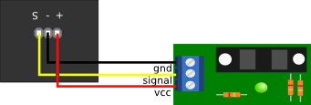
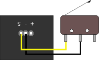
You can easily connect end stops to the board. There is support for 6 end stops (3 min, 3 max). For opto end stops you will need the S(ignal), - and + pins. For mechanical end stops the S(ignal) and – pins are sufficient.
The thermistors for reading heated bed and extruder temperature can be connected to the thermistor pins. Polarization is not an issue here.
Hooking up LCD
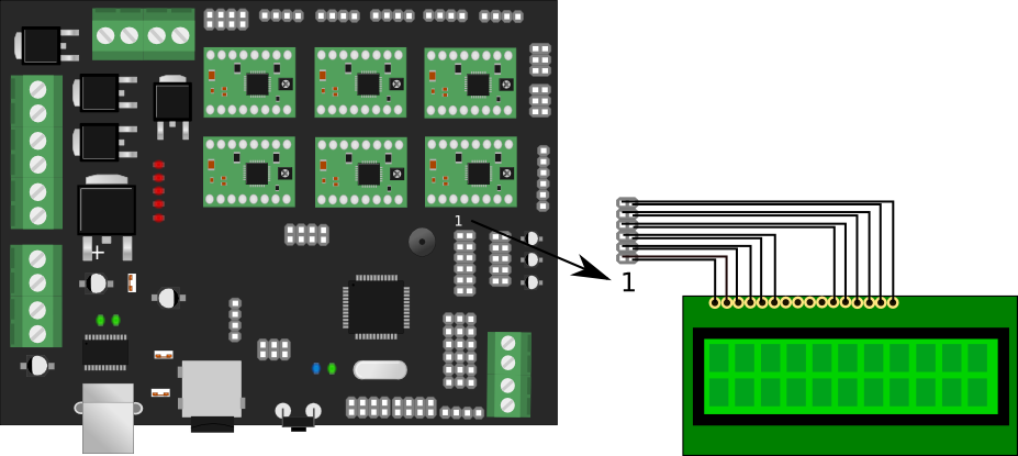
---WARNING--- Megatronics v2 Image provided Hooking up the LCD display is pretty easy, just follow the wiring diagram below. Note that the connector is turned 180 degrees in the image. The trimpot on the board sets the contrast of the LCD, if you don't see anything, you probably need to turn this.
Hooking up keypad
The keypad connects to the keypad header on the Megatronics. The wiring should be 1-to-1, meaning pin 1 is connected to pin 1, 2 to 2 etc.
Connecting end stop
You can connect either a opto end stops or a microswitch. Refer to you firmware on how to properly configure the firmware to use the end stop. The board has six headers for end stops, one for each stepper motor (or 2 for each axis). Each header has three pins:
1. + (5v output) 2. - (ground) 3. S (signal, closest to the atmega, directly connected to the atmega pin).
The following images show on ho to connect the end stops:
Using the DRV8825
Pololu released the DRV8825 Stepper Motor Driver Carrier a while ago. It has high current and a resolution of 1/32th step. The finer stepping produces significantly less noise than when using A4988. Search Youtube video tGd2ulVkDTM shows an example of how much more silent it is.
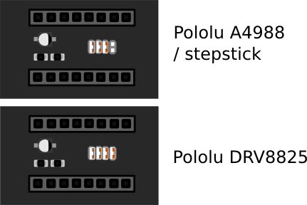
Megatronics v2 has support for this board and you can use it by simply setting a jumper. Under each stepper driver there are 4 jumpers that can be set. The left three set the resolution, depending on the type of stepper driver, the forth needs to be set for the DRV8825. For other stepper drivers this jumper must be removed.
Pololu has released an updated version of the DRV8825, that doesn't need the forth jumper
Note that the trim-pot should be oriented the opposite direction on DRV8825 vs A4988. Be sure to insert the driver with the correct orientation, or you'll need a new driver.
Pinouts
---WARNING--- Megatronics v2 image provided
AUX2/Keypad Header pinout:
header pin	atmega2560 pin (IDE)
1		5V
2		GND
3		PL4 	       (45)
4		PC4 	       (33)
5		PL5	       (44)
6		PC3	       (34)
7		PL6	       (43)
8		PC2	       (35)
9		PL7	       (42)
10		PC1	       (36)
AUX3 Header pinout:
header pin	atmega2560 pin (IDE)
1		5V
2		5V
3		PL0 	       (49)
4		PL1 	       (48)
5		PL2	       (47)
6		PL3	       (46)
7		GND
8		GND
FAQ
How do I use the fan2?
Add the following code to Marlin.main.cpp after line 5888 (or right after the second #endif // HAS_FAN):
     #if FAN2_PIN > -1
    case 806: //M806 Fan2 On
      if (code_seen('S')){
      analogWrite(7, constrain(code_value(),0,255));} //D7 is fan2_pin as in pins_MEGATRONICS_3.h
      else {
        analogWrite(7, 255);}
      break;
    case 807: //M807 Fan2 Off
      analogWrite(7, 0);
      break;
  #endif //FAN2_PIN
Sending M806 will now control fan 2.
Files
File:Megatronicsv2TestFirmware.zip
You can download Schematics and Board file of Memegatronics v3 (made with designspark-pcb) on reprapworld.com
