Pirated CupCake
Release status: Working
| Description | Cupcake as RepStrap
|
| License | |
| Author | |
| Contributors | |
| Based-on | |
| Categories | |
| CAD Models | |
| External Link |
CupCakeStrap Basics:
True DIY should be done on the lowest operating budget possible
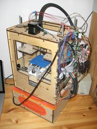
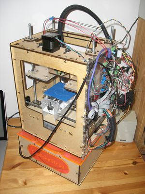
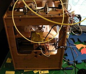
The Pirated CupCake, or "CupCakeStrap" is the high-school Senior Project of Benjamin Rockhold and Griffin Nicoll. It is a CupCake made from as close to scratch as possible, with the excepton of PCBs, Steppers, and PSU. Everything else was purchased in individual components from "The Internet" and a few local hardware stores. The plastic and plywood parts were laser-cut with Roosevelt High School's laser cutter and free material from donation. The CupCakeStrap is different from normal CupCakes in that it has been modified to reduce the price of some important parts, and it is not intended as a final machine. Instead, it will serve to print out parts for its successor, a RepRap Mendel-derivative (similarly modified for low cost). Thus, it is a RepStrap in spirit and a CupCake derivative in body.
If you don't have access to a laser cutter, perhaps the PrintItStickItCutit technique could be used to cut out the parts.
Contents
So, I bet you're asking "What's the attraction to building a Cupcake, with its smaller print area, high price, and odd naming?" Well, first off, it's the cutest of printing machines. Secondly, if it's not going to be purchased outright from Makerbot, it's really not very expensive at all. I'm not trying to say that the machines Makerbot sells are not excellent or are over priced, but the draw to make one from scratch is pretty strong given adequate time and resources.
Last but not least, for a beginner there is some educational value to study and copy a proven design (and its shortcomings).
The following is basic documentation, not in any real organized form. This is a to-do item :p
CupCakeStrap Hardware
Anything physical in the design of the CupCakeStrap that is unique or original.
Improvisations Made for Low-Price
We decided that in order to maintain a low price, we ought to custom-build more parts than we have to order in a completed state. Basically, these modifications were made anywhere we thought we could save a buck without reducing functionality.
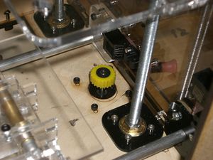
Acrylic Pulleys
To produce pulleys for zero cost, we found random belts from a scrapped printer (a BIG one, new printers use really small and useless belts) that looked similar to the ones used on the real CupCake, and then measured them. Using Inkscape, we performed a rotation of the tooth profile into a circle, and modified it to work with warping and stretching. Then we just lazzored them out of thin acrylic, and fused the layers together with an acrylic solvent. To attach to the motor, we used some random rubber things from the same printer, used to move paper. The rubber is a short tube, and very stiff. It was about 10mm in external diameter, and about the same as our motor's shaft in internal diameter. We insert the tube into the pulley, then press it onto the motor shaft. It's way, way stronger to hold in place than the motor can torque.
Cheap Linear Bearings
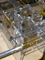
Rather than buy "real" linear bearings, we picked up some M8 Aluminum rod ($3 per meter) and some 8mm internal diameter brass tube (30cm for $4). With this, you get a sub-$10 brushing. We cut 6cm lengths of the brass tube and inserted them into a modified X stage (bearing holes reduced to diameter of brass rod). We made 3.5cm lengths for the Y stage, modified the same way. Essentially, we reinvented the brass brushing. These bearings work very well, even without lubricant. The primary source of friction is the motor on the XY stages and our motors are have excess torque, so friction is not a problem anyway. We feel these have a good chance and proving to have similar if not equivalent functionality as the proper ones originally intended for the Makerbot CupCake.
Improvisation Made for Increased Functionality
Now and then in the build process, we found things that we thought could be improved from the original CupCake. These are not particularly critical to the machine, but make it look better or work better (open to interpretation).
Motor Cut-Out
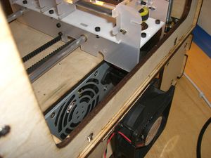
The motors we ordered (from Ebay) were more than 1cm longer than we expected, and so the Y-Stepper that rides the X-Carriage was too long to fit in the room given to it. We cut a large rectange out of the middle platform to correct this, and furthermore had to slide the PSU further forward in the machine. This means the PSU is 8cm in from the back plate. We have secured it with packing tape.
Extra Bearing Holders
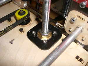
The original CupCake has bearings on the bottom end of the Z-Stage rods that stick up from the 4mm plywood used. These look kinda bad, so we added an extra few mm of acrylic cut to fit the bearing and to resemble the Z-Stage bearing capture layers. These extra layers are essentially cosmetic, but they also make it harder for the bearing to escape its hole. Theoretically, they could be augmented with a bearing-capture layer, and this would make the upper capture layers unnecessary. That might look nice.
Z-Platform Nut-locks
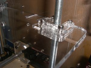
We decided that allowing the nuts to come lose from the Z-Stage was not something we wanted to see, even in the event of a head-crash. We added two more layers to the nut holder to fully trap it, a layer that mimics the platform's shape, and another Z-Guide part. We are going to have to modify the extruder-holding dinos to release the head in event of a crash, but that is a to-do item. In a head crash, the extruder lifts up on the bolts that hold it in place, which are set head-up in the extruder half-dinos. This also makes it easy to lift out to work on (which happens a lot).
In the future, we may exchange the Z-platform for a plywood one, as we have heard that after extended operation the acrylic ones can begin to warp from the heat.
These nut-locks have since been replaced by these neat printable things because honestly it made no sense.
Heated Build Plate
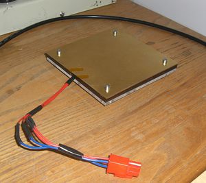
Once finally printing in ABS, we had little to no success with printing anything much larger in surface area than 2cm square, so we opted to build a heated plate to reduce the effects of warping. Somewhat based on the design of the heated plates that have been shown off in the reprap blogs and of the Makerbot-designed board, we decided to use extra extruder parts to construct our own design. Ours is simple, a 6 ohm length of nichrome wire in an "M" shape, affixed with high-temperature tape to a brass sheet, with a spare thermistor mounted in the center. Both heater and sensor are attached to a four-pin molex connector, which allows the plate to be swapped out rapidly (especially useful when a printed part sticks too well). The leads go to the extruder board, with the heater in mosfet port A and the thermistor attached to A-6 via a temperature sensor (2.0) board.
With the software configured correctly, ReplicatorG reads and controls the board perfectly. Our testing indicates that it can reach 100C within two minutes, though any temperature above 80C is acceptable.
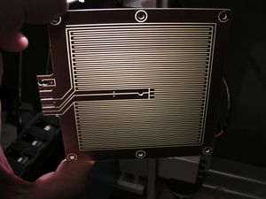
Alternative Milled Heated Build Plate
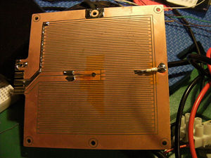
The first design pictured at right has a total resistance of 8 Ohm (expected: 2 to 4), presumably due to an unexpectedly thin copper layer. Split in half (2 x 4 Ohm resistors connected in parallel), the modified design gave a total resistance of 2 Ohm, as expected with
<math> R_{total} = \frac{R_1 \times R_2}{R_1 + R_2} </math>
This provides for a very convenient max. current draw of 6 Amperes (72W @12V), and rather fast (less than 1 minute for 25 to 65 C) heating times. A suitable thermistor was soldered in and covered with thermal paste, the plate was sandwiched between 2 kapton sheets, and covered with 1.5mm aluminium sheet.
CupCakeStrap Electronics+Software
Not too many modifications were made to the electronics for the CupCakeStrap, but it has an interesting history and mix of parts.
Electronics
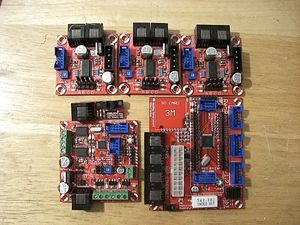
The CupCakeStrap was originally designed around the RepRap Generation 3 electronics, build by hand from components ordered from Mouser and Digikey. Due to backorder issues, we purchased the wrong linear regulators, and wholly left out the SD card slot, large 5v resistor, and the female headers. When powered on, one of the linear regulators (completely wrong for the job) sparked and smoked. The board it was attached to died (painfully I am sure), and the others were saved, and had the regulators amputated. Loss of the linear regulators proved hard to work around. A solution whereby we tapped the unused 5v supply from the PSU was proposed on the RepRap IRC, and this solution worked! By taking 5v from the ATX jack and feeding it to the output pad of the stepper boards we were able to operate the boards, now supplemented with a Stepper Driver 1.2 for the Z axis. After finally getting everything running, the CupCakeStrap performed two "prints," with no toolhead. However, on the third power-on one of the remaining 2.3 stepper boards began emitting ozone and shortly after a capacitor began sparking and then detonated with a puff of smoke and flame. The burn damage was significant, destroying the traces around the capacitor as well as two resistors. These parts were re-ordered, at some cost. Believing this board to be inert and with no immediate way to repair it, we decided to bite the bullet and purchase some completed boards as a replacement. We purchased three new stepper boards from Techzone, as they are new, interesting, and I do not think any other CupCake has ever been equipped with them. These boards are not yet reconciled into our price breakdown, as we have not decided if the accidental damages should be counted into the CupCakeStrap's price. They will probably not be. We were able to recover the burned board on the same day the new boards arrives, and we performed a test with it to be sure. However, the new boards proved to perform slightly better, and do not heat up as much as the 1.2 board. They are also really, really small. The original boards will be returned to CupCakeStrap after she has competed printing her first child, which will probably inherit all of the current electronics, leaving CupCakeStrap with An Arduino and various mismatched driver boards.
CupCakeStrap's extruder is currently a Plastruder mk4-type design, with pinch-wheel and gearmotor. This is the only extruder that will be able to be driven given our time constraints, though designs for a NEMA-23 stepper driven "Paxtruder" derivative have produced a prototype/functional design. Supposedly the newer CupCake firmware supports it, but we are not sure if using this design would be better than the current setup.
Alternative updated reprap electronics and software
Lanthan's build uses RAMPS_1.2 electronics running a june 2011 version of Tonokip (pre-Sprinter) firmware. Included here, not yet investigated why later versions do not appear to run.
Here is a working configuration with 16x microstepping on all stepper motors, "standard" cupcake pulleys on XY, ACME rods and small aluminium pulley on Z, a custom sliced wade's extruder using an M8 dremelled bolt and a "standard" purchased reprap hot end (see below)
Firmware settings: configuration.h Firmware snapshot
#ifndef PARAMETERS_H
#define PARAMETERS_H

// NO RS485/EXTRUDER CONTROLLER SUPPORT
// PLEASE VERIFY PIN ASSIGNMENTS FOR YOUR CONFIGURATION!!!!!!!
#define MOTHERBOARD 3 // ATMEGA168 = 0, SANGUINO = 1, MOTHERBOARD = 2, MEGA/RAMPS = 3, ATMEGA328 = 4, Gen6 = 5, Sanguinololu = 6

//Comment out to disable SD support
#define SDSUPPORT 1

//Min step delay in microseconds. If you are experiencing missing steps, try to raise the delay microseconds, but be aware this
// If you enable this, make sure STEP_DELAY_RATIO is disabled.
#define STEP_DELAY_MICROS 1

//Step delay over interval ratio. If you are still experiencing missing steps, try to uncomment the following line, but be aware this
//If you enable this, make sure STEP_DELAY_MICROS is disabled.
//#define STEP_DELAY_RATIO 0.25

//Comment this to disable ramp acceleration
#define RAMP_ACCELERATION 1

//Uncomment this to enable exponential acceleration
//#define EXP_ACCELERATION 1

//Acceleration settings
#ifdef RAMP_ACCELERATION
float min_units_per_second = 35.0; // the minimum feedrate
long max_acceleration_units_per_sq_second = 750; // Max acceleration in mm/s^2 for printing moves
long max_travel_acceleration_units_per_sq_second = 1500; // Max acceleration in mm/s^2 for travel moves
#endif
#ifdef EXP_ACCELERATION
float full_velocity_units = 10; // the units between minimum and G1 move feedrate
float travel_move_full_velocity_units = 10; // used for travel moves
float min_units_per_second = 35.0; // the minimum feedrate
float min_constant_speed_units = 2; // the minimum units of an accelerated move that must be done at constant speed
                                    // Note that if the move is shorter than this value, acceleration won't be perfomed,
                                    // but will be done at the minimum between min_units_per_seconds and move feedrate speeds.
#endif

// AD595 THERMOCOUPLE SUPPORT UNTESTED... USE WITH CAUTION!!!!

//PID settings:
//Uncomment the following line to enable PID support. This is untested and could be disastrous. Be careful.
//#define PIDTEMP 1
#ifdef PIDTEMP
#define PID_MAX 255 // limits current to nozzle
#define PID_INTEGRAL_DRIVE_MAX 220
#define PID_PGAIN 180 //100 is 1.0
#define PID_IGAIN 2 //100 is 1.0
#define PID_DGAIN 100 //100 is 1.0
#endif

//How often should the heater check for new temp readings, in milliseconds
#define HEATER_CHECK_INTERVAL 50
#define BED_CHECK_INTERVAL 5000

//Experimental temperature smoothing - only uncomment this if your temp readings are noisy
//#define SMOOTHING 1
//#define SMOOTHFACTOR 16 //best to use a power of two here - determines how many values are averaged together by the smoothing algorithm

//Experimental watchdog and minimal temp
//The watchdog waits for the watchperiod in milliseconds whenever an M104 or M109 increases the target temperature
//If the temperature has not increased at the end of that period, the target temperature is set to zero. It can be reset with another M104/M109
//#define WATCHPERIOD 5000 //5 seconds
//The minimal temperature defines the temperature below which the heater will not be enabled
#define MINTEMP 5

//Experimental max temp
//When temperature exceeds max temp, your bot will halt.
//This feature exists to protect your hotend from overheating accidentally, but *NOT* from thermistor short/failure!
//You should use MINTEMP for thermistor short/failure protection.
#define MAXTEMP 275

// Select one of these only to define how the nozzle temp is read.
#define HEATER_USES_THERMISTOR
//#define HEATER_USES_AD595
//#define HEATER_USES_MAX6675

// Select one of these only to define how the bed temp is read.
#define BED_USES_THERMISTOR
//#define BED_USES_AD595

// Calibration formulas
// e_extruded_steps_per_mm = e_feedstock_steps_per_mm * (desired_extrusion_diameter^2 / feedstock_diameter^2)
// new_axis_steps_per_mm = previous_axis_steps_per_mm * (test_distance_instructed/test_distance_traveled)
// units are in millimeters or whatever length unit you prefer: inches,football-fields,parsecs etc

//Calibration variables
// 20110724 from object dimensions measure
float x_steps_per_unit = 94.4269970200308;

// 20110724 from object dimensions measure
float y_steps_per_unit = 94.33009913 ;

// 20110724 from object dimensions measure
float z_steps_per_unit = 2568.67307692308 ;

float e_steps_per_unit = 503.443821338 ; // 20110723 yellow pla

float max_feedrate = 18000;

float max_z_feedrate = 120;

//For Inverting Stepper Enable Pins (Active Low) use 0, Non Inverting (Active High) use 1
const bool X_ENABLE_ON = 0;
const bool Y_ENABLE_ON = 0;
const bool Z_ENABLE_ON = 0;
const bool E_ENABLE_ON = 0;

//Disables axis when it's not being used.
const bool DISABLE_X = false;
const bool DISABLE_Y = false;
const bool DISABLE_Z = true;
const bool DISABLE_E = true;
//const bool DISABLE_E = false;

// const bool INVERT_X_DIR = false;
const bool INVERT_X_DIR = true;
const bool INVERT_Y_DIR = false;
const bool INVERT_Z_DIR = true;
const bool INVERT_E_DIR = false;

// Sets direction of endstops when homing; 1=MAX, -1=MIN
const int X_HOME_DIR = -1;
const int Y_HOME_DIR = -1;
const int Z_HOME_DIR = -1;


//Thermistor settings:

//Uncomment for 100k thermistor
#include "ThermistorTable_100k.h"

//Identical thermistors on heater and bed - use this if you have no heated bed or if the thermistors are the same on both:

#define BNUMTEMPS NUMTEMPS
#define bedtemptable temptable

//Endstop Settings
#define ENDSTOPPULLUPS 1
const bool ENDSTOPS_INVERTING = true;
const bool min_software_endstops = false; //If true, axis won't move to coordinates less than zero.
const bool max_software_endstops = false;  // 20110701 MK

const int X_MAX_LENGTH = 100;
const int Y_MAX_LENGTH = 100;
const int Z_MAX_LENGTH = 110;

#define BAUDRATE 115200

#endif
With this configuration, consistent results have been obtained with Repsnapper and the excellent Printrun, while Replicatorg has proven less stable, requires the fork for Ultimaker and some custom settings.
Software
While technically programmed as a CupCake right now, we plan to get it running with reprap FiveD firmware once a suitable stepper-driven extruder is constructed for it. Said extruder will probably be printed by the previous extruder (an awesome feat of self-upgrade!).
In programming the board we made a number of changes, though few were permanent.
- Inverting Z-enable to use a SMD1.2 when one SMD2.3 died.
- Elongating the bootloader's upload waiting time. Done as the first attempt to increase upload success with hacked cable.
- Adding a serial print to the extruder's startup - also for uploading timing.
- Flipping the extruder's motor pins, so that motor #1 has motor #2's pins, and vice versa. This was done because for no known reason, motor driver #1 stopped outputting anything. Turned out the things was not soldered properly, and two pads were not touching.
- Removing segments of the Arduino servo library, to clean up an error involving __Vector, or something. (Documented that on the FAQ page)
Price-Comparason
Our CupCakeStrap has, to date, cost less than $300. Compared to the CupCake's $750 price, this is pretty significant.
Original CupCake Price Breakdown:
The makerbot's $750 base price is just for:
- laser-cut plywood and laser-cut plastic = $200
- 3 NEMA 17 stepper motors and one big gearmotor = $75
- Nichrome wire, PTFE tube, and a milled barrel and nozzle ~ $30
- The reprap-derived electronics for controlling it. = $200
- Nuts, bolts, bearings, pulleys, metal rods and brushings and assorted metal parts, including some magnets ~ $250
- 1lb of ABS ~ $20
- Belts = $???
- M3 and M8 Allen keys = $???
You should note that those prices are what you would pay Makerbot for the individual items (as of march 31st), and do not properly represent their market value. It also totals more than $750.
The "deluxe" version adds $200 for the following:
- Some more laser cut plastic
- An ATX powersupply (like in a desktop computer)
- A USB to TTL cable to interface with it
- The cables that you need to connect the machine up it its own parts
- 5lbs more ABS
- Hex keys, wrenches, and some metal parts
- An SD card.
(Prices attached only where I could determine their actual cost)
Now, that's a respectable list, and probably worth every penny to someone who does not already have any of those items. However, if you are in a position to use or borrow any of those things, the price becomes a lot less appetizing. Thus, it is a good idea to treat the machine as a RepStrap, and not worry about building an exact clone of the Master CupCake in whose likeness all other CupCakes are forged.
CupCakeStrap Price Breakdown
The CupCakeStrap was built using a lot of scavenged parts, things that were laying around, and a huge quantity of freely available acrylic sheeting. This was especially useful as it meant we could simply laser cut a new part whenever a measurement was wrong. For example, we now have three complete sets of XY stage plastic and about a million failed pulleys.
- Laser-Cut plywood and acrylic = $0
- Belts = $0 (from scrapped printer)
- PSU = $0 (from scrapped computer)
- 3 NEMA 17 stepper motors and one big gearmotor = $35 (Ebay and a free gearmotor)
- Nichrome wire, PTFE tube, and a milled barrel and nozzle ~ $30
- Nuts, bolts, bearings, metal rods and brushings and assorted metal parts ~ $100
- RepRap Gen-3 PCBs ~ $20
- Electronics Components ~ $120
Note: One of the stepper boards exploded in construction, so we have replaced them with the Techzone version. This is not counted in the price, because "it should have worked"
- A USB to TTL cable to interface with it = $3 (Nokia phone cable, bought from Ebay and hacked)
- A USB cable that actually works = $25 (Bought from the Metrix Create Space when cable #1 stopped working)
- A 32MB SD card. = $0 Found one laying around, and we plan to simply hardwire it on.
Total ~ $278 This is a pretty rough estimate, pulled from my head. Probably less than this, but unsure.
CupCakeStrap ecological footprint and parts recycling
An additional benefit is the contribution to sustainability by recycling still functional parts. Lanthan's build reuses:
- 2 polished precision bars and 4 brass bushings from discarded printers for the x axis (improvement from the original cupcake design)
- 4 brass bushings for the y axis, equally from discarded printers (improvement from the original cupcake design)
- A thrashed scanner's fluorescent tube for interior lighting (warning: high voltage, needs installation precautions)
- An old computer power supply
Related Projects
The Original Makerbot CupCake CNC and the RepRap concept RepStrap.
Design Files for CupCakeStrap
Essentially, these are modified Makerbot CupCake design files, with extra bits added and some assorted parts removed. If I could go back and re-do the machine, I would. Sadly, our supplies of time are too low for that right now.
Downloads
Incoming... Slowly. Files may or may not be actually useful.
Alternative pathway (routerized cupcake)
There are more people around using CNC routers than laser cutters.
Routerized cupcake designs were released in 2010 by Pandelume: body panels, x-stage, y-stage and platform. Those were successfully adapted to 6.7 mm plywood and cut in late 2010 by Lanthan: Thingiverse, dxf files, g-code files.
A suitable wades extruder mashup was cut in summer 2011 and runs with robust and fully satisfying performance since some bolt-hobbing chores were dealt with. Video
