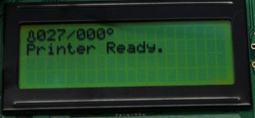
RAMPS LCD
|
English • العربية • български • català • čeština • Deutsch • Ελληνικά • español • فارسی • français • hrvatski • magyar • italiano • română • 日本語 • 한국어 • lietuvių • Nederlands • norsk • polski • português • русский • Türkçe • українська • 中文(中国大陆) • 中文(台灣) • עברית • azərbaycanca • |
Release status: working
| Description | Hook up a LCD display to your RAMPS setup
|
| License | GPL
|
| Author | |
| Contributors | |
| Based-on | |
| Categories | |
| CAD Models | |
| External Link |
Contents
Description
This page will guide you on how to hook up a LCD display to your RAMPS. Most LCD displays have 16 pins to control the display. They are either placed on the upper side of the PCB or on the left. Make sure you have the correct type of LCD display before starting.
Requirements
- LCD display preferably 20x4 or 20x2 characters/lines.
- RAMPS with Marlin firmware
- Some wiring
- A 10K trimpot is recommended for contrast adjustment
Where to get it
How to build it
We will have to connect 8 pins on the arduino to the LCD display. After that we need to configure Marlin to use the LCD display.
The following table show the pin assignments we are going to use:
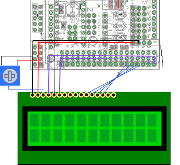
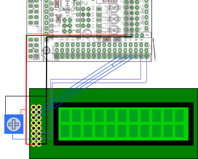
RAMPS pin LCD PIN Purpose GND 1 5V 2 3 (10K trimpot) Contrast D16 4 RS GND 5 R/W D17 6 Enable 7 Data 1 8 Data 2 9 Data 3 10 Data 4 23 11 Data 5 25 12 Data 6 27 13 Data 7 29 14 Data 8 15 Backlight + 16 Backlight -
Depending on the type of display you need to wire it differently. Here are two pictures showing how to wire two common types:
Adjust Marlin configuration
Marlin has LCD support by default, you just need to enable it in the configuration.
Find the following code in configuration.h:
 //LCD and SD support
 //#define ULTRA_LCD
Uncomment it, so it states:
 //LCD and SD support
 #define ULTRA_LCD
Find the following lines:
 #ifdef ULTRA_LCD
   #define LCD_WIDTH 16
   #define LCD_HEIGHT 2
 #endif
Change LCD_WIDTH and LCD_HEIGHT to match your display characters/lines.
Compile and upload. Happy printing!

