ReuseDaBox
Release status: Building it as I go...
Contents
Overview
The thought occurred to me yesterday, after discussing the possible design and construction of a 3D printer with a colleague at work who already owns one which he built from a kit. To each his own of course, but being a diehard engineer, I figure that building a RepStrap would be way more fun, and much more of a learning experience. Looking around this wiki it seemed a WolfStrap would be the most reuseable way to go, since I have an old TV cabinet in my garden shed which forms a perfect sturdy wooden frame for what I wish to create. On top of that, it already holds at least four drawer guides which can be reused for the various translation movements!
Actually, I've decided to go an alternate route, and build a Prusa I3 first to get the hang of things. Then, once that is running, I will be able to use it to print the required parts to finish this project.
Phase 1: making the cabinet a solid base
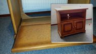
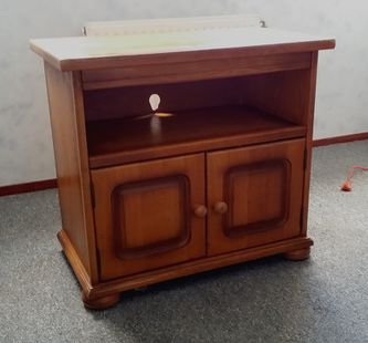
The base of this design can be just about any rectangular cabinet, that you deem will provide sufficient work volume. I chose an old TV cabinet from the days that TV's were still massive beasts which required superhuman strength to lift, or cooperation of two humans like in Dire Strait's awesome hit...
The turntable on the top unfortunately did not have sufficient rigidity in its sliders to serve for the motion train of the extruder head, but the board halfway did have good supports. So I removed the top, the backside and the middle shelf. By cutting a rounded rectangle in the hind board, it maintained its support capacity, and screwed back in that gave the cabinet its left to right sturdiness again.
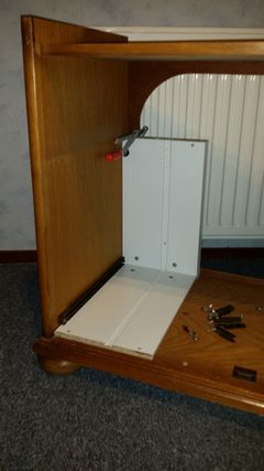
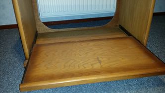
My board already had drawer guides, but if yours doesn't, you could just make it a bit less wide and mount drawer guides you have lying around, or can acquire from a local DIY store. My effort in making this design however is to keep the spirit of RepRap, in reusing as much as possible. (even the turntable might go to a friend wanting to make solar panels turn to the sun...
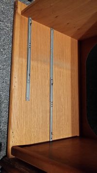
In order to perfectly align both drawer guides, I spaced them from the bottom of the cabinet and the backside by inserting a few temporary boards while I screwed them in place. This makes certain that the bed will move smoothly. Measuring the base position against the fully extended position, it gave me about 275 mm work space from back to front. So if I can mount the mechanical parts for the Y movement outside on the back of the cabinet, I'll actually have that much working room!
Phase 2: creating room to maneuver
I may have to do some reinforcing of the top board, because time has left it a bit sagged from the weight of those TV monsters. But it will always be a nice place to put the spools of material, and the old reused PC that will eventually drive it!
To my engineering eye, mounting dual stepper motors left and right on the back of the cabinet, driving threaded rods will ensure the bed moves perfectly forward. I also choose to use dual end switches, because I like the better fail safe it gives you over just one home switch. And rather than use new switches, it will even be possible to just use two paper clips and screws with washers. But maybe that is pushing reuse a bit too far! ;-)
As for reusing old mechanical parts versus designing to be 3D printed parts is something I will think about next. Perhaps I can get my 3D printer owning colleague to print me the needed parts for this project if I pay for the needed base material...
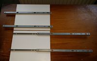
And luck keeps falling into my lap: just now I remembered that I'd recently taken apart two cabinets with drawers that my youngest daughter no longer wanted because she got a new one to stash all her clothes. It turns out the drawing guides in there were far too weak to support the weight of the drawers orthogonal to their direction of movement, but I had exactly five working ones left. And four of those, mounted two by two left and right inside the cabinet gave me a Z-axis movement of about 239 mm! Because the cabinet measures 520 mm inside height, I still have 281 mm headroom for the mechanics!
Of course, if I decide my Z-Axis isn't enough, then taking out part of the top board might solve that, but then I'd have to find me longer guides... And quite frankly, I think this is sufficient for now.
So what's next? How about figuring out the last of my movement constraints? Just how much extra space do I need left-right inside of the XZ head movement? I have 670 mm space between the left and right guides, but just how much will be gobbled up by the extruder head, and the stuff that moves it left to right? Ah well, we'll see later, let me just get myself some "Moore input" in order to tackle this one!
After some looking around, it seems the stepper motors will set me back about 75 Euros, since I wish to use two for the Y axis, two for the Z-axis, and one for the X-axis. Initially the extruder will have only one nozzle, so that is number six, at 12 euro a piece. I'm going for the FL35ST36-1004A, which has a drive current of 1.25 Amps per coil and a torque of 0.14 Nm. I figure that's enough, but if you think otherwise, feel free to step in... ;-)
The stepper motors for the Z movement will be bolted to the top board, which gives them a secure position. I still have some rubber pads lying around, which might make vibration noise less, but we'll see.
I guess the stepper motor for the X axis will be driving one threaded rod, and thus will be mounted lengthwise. That means the 41 mm of the motor and the length of the shaft must be subtracted from my initial inside length, as well as the thickness of the mounts on both sides. Let's make that a total of about 120 mm, so I have a complete working volume of 550x278x239 mm!
Phase 3: Building the XZ Head positioning assembly
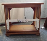
Ok, today's work on 'da Box' will be the XZ Head train, in as far as I can get it done without the stepper motors. Basically I just took the boards of a busted drawer of Melanie's clothes cabinet, and made them into platforms for the slide guides left and right. Keep in mind that you have to unscrew the guides first, in order to get them mounted to the boards. For the lateral support, I had the front of the drawers, but unfortunately that proved just a bit too wide. So I cut out the mid section, and after screwing them to the side plates, I put a small board top center, that could hold the name plate...
I thought about making the front closed, but decided against it because technology may be admired, and the dual stepper drive will make sure both ends move simultaneously anyway...
As for the back side of the XZ Head assembly, I decided not to connect the side boards yet. Maybe later I'll need a support there to add further mechanical parts, but for now open space seems like the most viable option.
The next bit will probably be figuring out just how the threaded rods will be mounted, in such a way as to make sure they do not limit the working volume any further, and do not interfere with one another. Most logical will be to start with the Y movement, for which the stepper motors can be fitted to the back support of the cabinet. There should be plenty of space to mount the rods in such a way that they don't extend outside the front of the cabinet. The same goes for the Z-axis, where the steppers can be mounted either against the top board, or on top of it. I will have to design supports however, for the eds of the rods that are not connected to the stepper motors.
The most challenging so far will probably be the X axis, since I wish to make that with a threaded rod as well, rather than a drive belt. Does anyone have any idea whether that can be driven fast enough?
Phase 4: Designing the printable parts
After a few weeks of relative silence, I found my colleague willing to print me any needed parts. So designing was started, not based on the Google Sketchup tool, but using OpenSCAD. Somehow, manipulation 3D objects to me is easier if I can simply hard code the coordinates rather than try to manipulate them with a 3D interface on a 2D screen...
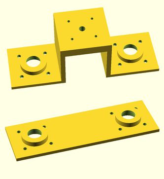
First of all, the head moving assembly, which I decided might well consist of two M8 threaded rods, fixed to the Z-sled by printed plastic parts. One end would have a stepper motor in between, which drives both axes through cogs. See the image on the right....
Materials to buy rather than reuse
It's been a while since I soldered my own electronics, but I should still be able to do that. But rather than etch the boards myself, I'll order them, and buy ready-assembled for tricky SMD stuff
1 x Gen7 v1.5 PCB, including developer donation EUR 16.50
1 x Gen7 v1.5 Components Kit (with ATmega1284P and bootloader) EUR 25.50
1 x Gen7 v1.5 Connectors Kit EUR 13.50
3 x Gen7 Opto Endstop PCB (one piece) EUR 6.00
3 x Gen7 Opto Endstop Parts Kit (for one endstop) EUR 6.00
5 X SevenSwitch 1.2 PCB, including developer donation EUR 15.00
5 X SevenSwitch 1.2 Parts Kit (Components & Connectors) EUR 16.20
1 x Shipping International EUR 5.00
5 x A4988 StepSticks Botronicz EUR 30.94
6 x FL35ST36-1004A Nema 14 stepper motor EUR 72.00
2 x threaded rod M8 length 280 mm
2 x threaded rod M8 length 240 mm
1 x threaded rod M8 length 550 mm
(basically two 1 meter lengths) EUR 10.00
Ok, so it'll take a bit over 200 Euros...
