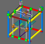
SCOUTcorexy
Release status: Concept
| Description | An easy DIY CoreXY 3D printer with square tube frame (ALU or Steel) that doesn't need precise cutting yet is a sturdy construction and sports a number of error-forgiving features that can compensate for many errors that are unavoidable in a DIY build so that the end result is a precise, dependable machine.
|
| License | |
| Author | |
| Contributors | |
| Based-on | |
| Categories | |
| CAD Models | |
| External Link |
The SCOUTcorexy is an easy DIY-able CoreXY reprap 3D printer that uses square tubes in a "Scout tower" fashion to rely on the factory-made straight faces of the square tube rather than relying on a straight cut made by the builder. This has the advantage that each square tube becomes the corner bracket of another square tube in the same node, rendering the need for brackets unnecessary. The machine will have all the advantages of the CoreXY genre it is based on (printing at high resolutions and high speeds, easy assembly, fixed XY stepper motors, easily enclosing frame for high temp printing) but it will add to those some features of its own: 3-rods, dual support belt-based Z (no wobble like most threaded rod/leadscrew designs, no slop like cantilevered designs), single tensioning mechanism for both XY belts for less guess-work, very precise 4-points adjustment clamps for both Y rods and Z rods for a perfect alignment and squaring of the smooth rods should any error in the squareness of the frame be inadvertently introduced and many more that I will describe below or in updates. The critical mechanical and electronics will be separate from the box in a first iteration and the bed will not be heated for this very first concept.
Contents
Goals
- Open-Source/Free design
- Anybody can build it with a cordless drill, a hacksaw and a screwdriver. The 3D printed parts need to be sourced or printed on another 3D printer.
- Very few components need to be precise (smooth rods), all other parameters of the printer will sport adjusting elements that can compensate for drill bits run-off, imprecise hacksaw end cuts, etc
- All 3D-printed parts will not rely solely on the plastic itself but will have bolts and other elements that will improve the mechanical characteristics and so the precision of the whole 3D printer, albeit being built with simple, error-prone techniques (ex: the Y Carriages have back-supported rods thus relieving the stress due to the tension in the corexy belt system)
- All 3D-printed parts will rely on a self-designed square-clamp system that will be repeated throughout the design so that each plastic part attaches to the square tube frame in the same fashion.
- Due to the self-designed square clamp many variations of the square tube dimensions can be accommodated, especially variations in the thickness of the paint should painted or otherwise covered square tubes be used. The plan is to be able to use the same parts for 25x25mm tubes and even maybe for 30x30, using just longer bolts to fasten the clamps
- Non-Cantilevered Z platform
- Dual Hotend, with Dual-bowden for the prototype and Bowden-Direct combo for the second iteration
- Delta-style Flying-Extruder at some point in the future
- At least 250x250x250mm build volume.
Features
- DIY-friendly construction and assembly (can be built with a cordless drill and a hacksaw on the kitchen table)
- Square tube structure based on 20x20 Steel or Aluminum (even Makerbeam/Misumi 20x20mm extrusion can be used as the square clamps can be fitted to any square tube)
- The holes of the frame will be drilled using a technique that will not require perfectly 90 deg drilling (the technique will be explained later)
- Stacked variant of CoreXY that eliminates the belt crossing and its associated issues
- Emphasis on using 3D-printed parts and being easily hackable/upgradeable
- Dual-Bowden extruder for the first iteration (fast production of parts needs a large nozzle for infills while the "shell" should be smooth and done with very fine nozzle for high resolution)
- Low moving mass — all motors stationary.
- No specialized tools or equipment necessary for assembly (accessible)
- LM10UU linear bearings for X,Y and Z (initially the rod for X axis was calculated for static loads to be 8mm but I've changed to 10mm to compensate better for the dynamic loads and higher speeds)
TODO (for future iterations)
- All hardware and electronics, including the filament spool will be integrated within the frame.
- Heated printbed
Hardware Specifications
[tbd]
Bill of Materials
[tbd]
Printed Parts
[tbd]
Tools
Recommended: obtain a small geared power drill or a screwdriver with a standard hexagonal tool-bit adapter
- Allen keys: 1.5mm, 2.0mm, 3.0mm, 4.0mm (these are for the MK8 drive gear, GT2 gears, etc. - get 2 of the smaller ones because they tend to wear out)
- Screwdrivers: electrical (for the EC), flat-head and/or pozidrive (for M3 screws)
- Another 3D printer capable of 0.20mm layer height (your own or use someone else's)
- Keyfile set (round, square, flat, arc, triangular etc.) and small Craft knife (for trimming 3D parts: keyfiles can also be useful for filing inside extrusion ends, so that M3 hex nuts fit properly)
- Method for cutting extrusions to length (see below)
- Hacksaw with blade that is made for metal cutting
- Soldering iron, solder, stand and sponge (usual deal for soldering)
Development
Discussion on the reprap forum starting at about this post: http://forums.reprap.org/read.php?397,587274,635699#msg-635699
Dimensioning and calculations for the smooth rods are about here: http://forums.reprap.org/read.php?1,588422,588585#msg-588585
Version 1.0
[tbd]
Gallery
[tbd]
Videos
[tbd]
