Stepper Motor Driver 1.0
This page describes something which is no longer the most recent version. For the replacement version see: Stepper Motor Driver 2.3
Overview
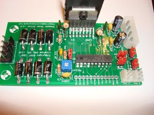
<div class="thumb tright"></div>This board allows you to control one stepper motor, as well as receive input from two limit switches. It is based around the L297/L298 stepper driver combo. The L297 takes the signals from your microprocessor and translates them into stepping signals to send to the L298 which actually drives your stepper motor. The L298 is capable of driving up to 2A per coil. One interesting feature of the L297 is its current sensing and 'chopping' abilities. The L297 will sense the amount of current flowing through the coils, and will 'chop' the signal to the L298 so that the average current flowing is the desired amount. You can configure this current by setting the trimpot on the board.
- You'll need a soldering toolkit to do most of this.
- Read our Electronics Fabrication Guide if you're new.
Files
You can download the release file from SourceForge that has a bunch of helpful files for this board. It contains:
- GERBER files for getting it manufactured
- PDF files of the schematic, copper layers, and silkscreen
- Eagle source files for modification
- 3D rendered image as well as POVRay scene file
- exerciser code to test your board.
Interface
Input
| Pin | Function |
| GND | Connect this to Arduino to share a common ground. |
| Step | A pulse on this line will make the stepper motor advance one step in the desired direction. |
| Dir | If this pin is high, the motor will rotate forward, low it will rotate backwards. |
| Enable | Optional This pin allows you to turn the motor on and off. This is also controlled by the 'Enable' jumper. A high signal means on, low signal means off |
| Reset | Optional A strobe (low pulse) will signal the L297 to reset. It doesn't really do much to be honest. |
| H/F | Optional This controls the stepping mode. High means half stepping, Low means full stepping. This is also controlled by the 'Steps' jumper. |
| CNTL | Optional This controls which sense lines to operate on: INH or ABCD. It is rarely used and more info is found in the L297 datasheet. |
| SYNC | In slave mode, you will need to connect this to the SYNC of a board set to be master. |
Output
The L298 is rated for 2A per coil, so if your stepper motor drives more than that, you should adjust the chopper so that it delivers less current than that.
| Pin | Function |
| Min | This is the signal from the 'X min' sensor. high means open, low means closed |
| Max | This is the signal from the 'X max' sensor. high means open, low means closed |
| Stepper | This is the output for the stepper motor. From top to bottom, the coils are: A+/A-/B+/B- |
Jumpers
There are certain things that can be configured on this board by setting jumpers. Make sure you set all the required jumpers.
S M
This is the slave/master jumper setting. The master generates the oscillation, as well as sync pulses for the other boards. You will want to pick one board as the master, and set the rest to be slaves. It really doesn't matter which is master and which is slave, so long as there is only one master, and the rest of the boards are slaves.
Steps
This is how you select half vs. full stepping. Half stepping means the stepper takes twice as many steps, whereas full stepping means the stepper takes its normal number of steps. Half stepping is highly recommended.
Control
This setting controls which lines the current chopping works on. If you ware driving a stepper motor, you will always want to use ABCD. This jumper will likely be removed in the next release.
Reset
This jumper basically tells the board not to reset. You will generally want to always leave a jumper on this set of pins. This jumper will also likely go away in the next version of the board.
Enable
This jumper tells the board to enable torque on the motors. If you are planning on controlling the torque from the inputs, then you will want to remove this jumper. This jumper will probably be replaced with a pullup resistor in the next version of the board.
Current Adjustment
The board allows you to control the amount of current flowing through the coils by adjusting a trimpot located on teh board next to the input pins. Simply turn the trimpot one direction to get the minimum current, and the other direction to get maximum current. Generally this will be clockwise/counter clockwise, but it will be obvious which is which as you adjust the current with the motor running. Adjusting it to the lowest setting will cause the motor to stop turning. Generally, you will want to adjust this to the lowest setting you need that will still turn the motor. That will reduce power usage, and will prevent your motor from overheating.
Circuit Board
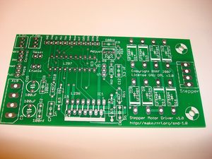
<div class="thumb tright"></div>You can either buy this PCB from the RepRap Research Foundation, or you can make your own. The image above shows the professionally manufactured PCB ready for soldering. It's also cheap, only $7.50 USD.
Components
Refer to the part list generator for information on where to get the stuff you need.
<iframe width='600' height='600' frameborder='0' src='http://spreadsheets.google.com/pub?key=pmEMxYRcQzzATwbOb71BmGA&output=html&gid=23&single=true&widget=true'></iframe>
Known Bugs
There are no known bugs at this time. If you find any, please contact us in the forums.
Build Process
R10, R11, R12, R15
Solder these resistors in the appropriate places. Make sure you double check the color codes to make sure you're putting the proper resistor in the proper place. You can insert the resistor in any orientation into the board.
Socket
Now is a good time to solder the DIP socket into the board. Try to get it as flush with the board as possible. I like to solder a corner pin, then solder the opposite corner pin to lock the socket into place as I solder the rest.
D9-D16
First insert all the diodes into place. Bend the leads with your hands or with some pliers, as close to the body as you can. Then, insert the component so that the band one one end matches up with the band on the silkscreen. Make sure you get these right!!! After you have inserted all the components, flip the board and solder them all in.
R9
This is the trim pot. There are numbers on it, that match up with the numbers on the silkscreen. Insert it accordingly, and solder it in.
C2, C8, C9
These are the 100nF ceramic capacitors. They will have something like '104' written on the side. Solder them into place, orientation does not matter.
C6, C7
These are the 1nF ceramic capacitors. They will have something like '102' written on the side. Solder them into place, orientation does not matter.
C12
This is the 3.3nF ceramic capacitor. It will have something like '332' written on the side. Solder it into place next to the trim pot. Orientation does not matter.
JP1-JP6, JP14
These are the headers for the jumpers. Break off the appropriate number of pins from the pin strip and solder them into place. Take care to make sure you solder them in straight.
C3, C15
These are the electrolytic capacitors. They have only one orientation you can solder them in. One side is marked negative (with '-' going down one side.) The other lead is longer and should be inserted into the hole marked '+'.
IC1
This is the L298 chip. You will only be able to insert it into the board in one orientation. Once you have inserted it, solder it in. Take care not to use too much solder that it doesn't bleed through and bridge where the leads come together.
R7, R8
These are the larger, power sensing resistors. They will not fit laying flat, so bend them so they are inserted at an angle. Orientation does not matter.
X2
This is the stepper header. Solder it with the tabs facing the inside of the board. Make sure it is nice and flush with the board.
Input Wires
Take 60 - 90 cm [2 - 3 feet] of Cat 6 ethernet cable, and remove about 25 mm [1"] of the sheath from it to expose the twisted pairs. Trim about 6 mm [1/4"] from the end of each of the wires, and insert them into the respective holes for the pins. Then solder each wire into its hole. Trim the ends if required.
| Color | Input |
| GND | Brown |
Test Your Board
Now we have to test the board. Its very easy, and consists of a few steps.
Connect Power to Board
Always turn your power supply off before plugging it in. It won't fry things most of the time... but all it takes is once to damage things.
Simply take your hacked PC power supply and plug a power connector into board. There is no power indicator, but as long as nothing starts smoking, you should be fine.
Turn your power supply off while you plug boards together!
Wire up test devices
Connect Board to Arduino.
This part is very easy. Strip 1/4" from the end of the input wires (You used Cat6 ethernet innards right???) Now, insert the end of each input into the correct pin on the Arduino, and then connect the Ground pin to Ground on Arduino. Use the table below to determine what pins to hook up to what:
| Board Pin | Arduino Pin |
| STEP | 4 |
| DIR | 5 |
| GND | Ground |
Upload Firmware to Arduino
Now, feel free to turn on the power to your power supply. Next, open the Arduino software, and upload the files located in the exerciser directory in the file that you downloaded above. After the firmware has compiled and uploaded, the Arduino will restart and the exerciser will begin shortly.
The basic way the motor exerciser works is this:
- The stepper will take 400 steps in one direction
- The stepper will take 400 steps in the opposite direction
- The speed will increase or decrease.
The stepper exerciser will gradually increase/decrease the stepper motor to show a wide range of possible speeds and movements. It will do 400 steps in each direction at each speed.
Troubleshooting
- First, check to see that you have supplied power to the board.
- If that doesn't work, check that you have the board wired up correctly to the Arduino.
- If the motor does not move at all, then check your circuit for shorts and dry joints.
- If the motor does not move, but is very jerky, then you have miswired the stepper to the board. Simply reverse the polarity on one coil to make it function properly. (eg. switch A+ with A-)

