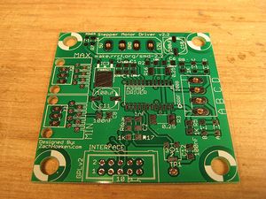
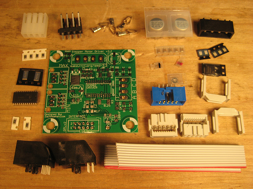
Stepper Motor Driver 2.2
This page describes something which is no longer the most recent version. For the replacement version see: Stepper Motor Driver 2.3
Contents
Overview
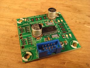
This board allows you to control one stepper motor, as well as receive input from two limit switches. It is based around the Allegro A3982 Stepper Motor Driver with Translator. The A3982 is capable of driving up to 2A per coil. This board was designed to improve upon and replace the v1.x series of stepper drivers which are based upon the venerable L297/L298 stepper drivers. The A3982 offers a number of improvements:
- Only one chip to solder, as opposed to the two chip L297/L298 combo
- Superior DMOS technology (no heatsink required!)
- Built-in diodes and synchronous rectification (no large diode array!)
- Much cheaper and smaller than the L297/L298 (about $10 cheaper, total!)
The downside is that the board is mostly SMT, although we made a conscious design decision to stick with some of the largest and easiest to solder SMT components on the market. We used 1206 sized resistors and the A3982 itself is in a SOIC package. The board is very easy to put together, even for a beginner. Using a technique such as solder paste + hot plate, the board becomes ridiculously easy to solder. I found that it is much easier to solder SMT boards in this fashion than to solder pin after pin manually with through-hole components.
- You'll need a soldering toolkit to do most of this.
- You'll also need a SMT soldering toolkit to construct this board.
- Read our Electronics Fabrication Guide if you're new.
Get It!
Raw Components
Files
You can download the release file from SourceForge that has a bunch of helpful files for this board. It contains:
- GERBER files for getting it manufactured
- PDF files of the schematic, copper layers, and silkscreen
- Eagle source files for modification
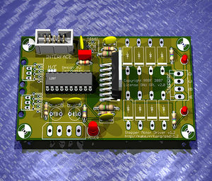
- 3D rendered image as well as POVRay scene file
- exerciser code to test your board.
Schematic
Sorry, check the eagle file.
Configuration
Current Adjustment
The board allows you to control the amount of current flowing through the coils by adjusting a trimpot located on the board next to the 'Interface' connector. Simply turn the trimpot one direction to get the minimum current, and the other direction to get maximum current. Generally this will be clockwise/counter clockwise, but it will be obvious which is which as you adjust the current with the motor running. Adjusting it to the lowest setting will cause the motor to stop turning. Generally, you will want to adjust this to the lowest setting you need that will still turn the motor. That will reduce power usage, and will prevent your motor from overheating.
Interface
IDC Connector
| Pin | Name | Function |
| 1 | GND | Connect this to Arduino to share a common ground. |
| 2 | GND | Connect this to Arduino to share a common ground. |
| 3 | Step | A pulse on this line will make the stepper motor advance one step in the desired direction. |
| 4 | Dir | If this pin is high, the motor will rotate forward, low it will rotate backwards. |
| 5 | Enable | This pin allows you to turn the motor on and off. By default it is pulled high. A high signal means on, low signal means off |
| 6 | Min | This is the signal from the 'min' sensor. The definitions of high/low are determined by your opto endstop. |
| 7 | Max | This is the signal from the 'max' sensor. The definitions of high/low are determined by your opto endstop. |
| 8 | GND | Connect this to Arduino to share a common ground. |
| 9 | GND | Connect this to Arduino to share a common ground. |
| 10 | GND | Connect this to Arduino to share a common ground. |
Minimum and Maximum Connectors
Say it with me:
The Stepper Motor v2.2 design does not support ethernet!
The Stepper Motor v2.2 design does not support ethernet!
The Stepper Motor v2.2 design does not support ethernet!
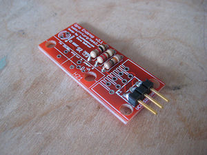
What we are doing is hijacking a common and very cheap connector for our own purposes. RJ45 patch cables and jacks are ubiquitous, versatile, robust, and cheap. We've considered and rejected many other connector technologies (RJ11, 3.5mm audio cables, etc) but in the end, RJ45 is the best for our needs. If you have another source of high quality premade cables (that we have not already rejected) please bring it to our attention in the forums. Please do not complain about being forced to use these cables, as there is a simple on-board alternative (see below).
Below you will find a pin out table containing the pin-out information on a standard RJ45 patch cable.
| Pin | Color | Function |
| 4 and 5 | Blue and Blue/White | 5V supply |
| 6 | Green | Signal |
| 7 and 8 | Brown and Brown/White | Ground |
.100" Spaced Header
In order to maintain backwards compatibility, as well as giving the user the freedom to chose their desired connector technology, we have included a standard, .100" pitch connector footprint that you may populate as desired. The pins are clearly labeled, and you may wire it however you like. You can solder wires directly to the board, solder in right-angle headers, normal headers, or any other number of technologies. Its up to you as a user to decide. Shown here is an example of using a right-angle .100" spaced header.
Note: No, that's not our board, but the footprint is exactly the same.
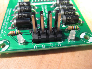
Output
The A3982 is rated for 2A per coil, so if your stepper motor drives more than that, you should adjust the chopper so that it delivers less current than that.
| Pin | Function |
| A | This is the 'positive' end of coil 1 |
| B | This is the 'negative' end of coil 1 |
| C | This is the 'positive' end of coil 2 |
| D | This is the 'negative' end of coil 2 |
We have a page with full info on wiring your stepper motor for use with this board.
Circuit Board
You can either buy this PCB from the RepRap Research Foundation, or you can make your own. The image above shows the professionally manufactured PCB ready for soldering. Its also cheap, only $5.00 USD.
Components
Build Process
Sorry, never completed. ;)
Test Your Board
Now we have to test the board. Its very easy, and consists of a few steps.
Connect Power to Board
Always turn your power supply off before plugging it in. It won't fry things most of the time... but all it takes is once to damage things.
Simply take your AT power supply and plug a power connector into the board, and turn it on. The green LED next to the connector should light up. If it doesn't, check its polarity and bust out your multimeter!
Turn your power supply off while you plug boards together!
Give it a test drive.
Connect Board to Arduino.
This part is very easy. Use the table below to determine what pins to hook up to what. Plug the IDC cable into the blue socket on the stepper controller board. If you look into the holes of the IDC plug, with the red stripe away from you, the top-right pin is #1. The pin to its left is #2. The pin one row closer to you from #1 is #3. The pin closer to you from #2 is #4. Plug three jumper wires from the IDC connector into the associated Arduino pin:
| Board Pin | IDC | Arduino Pin |
| STEP | 3 | 4 |
| DIR | 4 | 5 |
| ENABLE | 5 | 6 |
| GND | 2 | Ground |
Upload Firmware to Arduino
Now, feel free to turn on the power to your power supply. Next, open the Arduino software, copy the code below into your sketch and upload it. After the firmware has compiled and uploaded, the Arduino will restart and the exerciser will begin shortly.
#define stepPin 4
#define dirPin 5

void setup() {
  Serial.begin(9600);
  Serial.println("Starting stepper exerciser.");

  pinMode(stepPin, OUTPUT);
  pinMode(dirPin, OUTPUT);

  digitalWrite(dirPin, HIGH);
  digitalWrite(stepPin, LOW);
}

void loop() {
  int i, j;

  for (i=1000; i>=200; i-=100) {
    Serial.print("Speed: ");
    Serial.println(i);

    for (j=0; j<2000; j++) {
      digitalWrite(stepPin, HIGH);
      delayMicroseconds(i);
      digitalWrite(stepPin, LOW);
      delayMicroseconds(i);
    }

    delay(500);
    digitalWrite(dirPin, !digitalRead(dirPin));

    for (j=0; j<2000; j++) {
      digitalWrite(stepPin, HIGH);
      delayMicroseconds(i);
      digitalWrite(stepPin, LOW);
      delayMicroseconds(i);
    }

    delay(1000);
    Serial.println("Switching directions.");
    digitalWrite(dirPin, !digitalRead(dirPin));
  }
}
The basic way the motor exerciser works is this:
- The stepper will take 2000 steps in one direction
- The stepper will take 2000 steps in the opposite direction
- The speed will increase or decrease.
The stepper exerciser will gradually increase/decrease the stepper motor to show a wide range of possible speeds and movements. It will do 2000 steps in each direction at each speed.
The higher speeds might be too high for your stepper, the motor will then, although correctly connected, just beep.
You can easily visually verify that the stepper motor driver is working after you do this, as the LED's next to the stepper driver will both light up and will flicker. This is because the LED's are switching from on to off very rapidly. If this is happening, then congratulations: your stepper driver board is a success!
Hook up a stepper motor
You'll need a stepper motor to drive at this point.
Find a stepper motor that you have wired up to a .156" pitch connector. You can view wiring diagrams for various stepper motors if you have not wired any up yet.
Make sure the power to your driver board is off and insert the connector. Reset the Arduino board and turn the power on for your power supply. After a few seconds, your stepper motor should spring to life. When it does, do a little dance because you've just cleared the hardest hurdle in making a robot that can do some amazing things*.
You probably want to optimize for minimum power consumption, which stops the chip from getting too hot and cuts down on noise. Adjust the trim potentiometer power all the way anticlockwise, which basically cuts off the drive current. Now tweak it clockwise until the motor performs as desired reliably plus a tiny bit extra. There, done. If you want to get fancy, there's a test point just below the trimpot which you can measure the voltage on. If you know how to do that properly, please write up the process for the rest of us.
- Maybe. ;)
Troubleshooting
- First, check to see that you have supplied power to the board.
- If that doesn't work, check that you have the board wired up correctly to the Arduino.
- If the motor does not move at all, then check your circuit for shorts and dry joints.
- If your board checks OK and you have power lights, tweak the trim potentiometer briefly to the right. Any improvement?
- If the motor does move, but is very jerky, then you have miswired the stepper to the board. Simply reverse the polarity on one coil to make it function properly. (eg. switch A with B)
History
Changelog
- Switched to the A3982 stepper driver
- Hand routed all the power and signal traces
- Modified hole spacing to be compatible with a NEMA23 motor
- Lots and lots of tiny tweaks.
Previous Versions
- A redesign of the Stepper Motor Driver v2.1
- Which was a complete redesign of the Stepper Motor Driver v2.0
- Which was an even more complete redesign of the old Stepper Motor Driver v1.2
