Stepper motor/ru
|
English • العربية • български • català • čeština • Deutsch • Ελληνικά • español • فارسی • français • hrvatski • magyar • italiano • română • 日本語 • 한국어 • lietuvių • Nederlands • norsk • polski • português • русский • Türkçe • українська • 中文(中国大陆) • 中文(台灣) • עברית • azərbaycanca • |
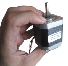
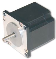
A stepper motor is one kind of electric motor used in the robotics industry. Stepper motors move a known interval for each pulse of power. These pulses of power are provided by a stepper motor driver and is referred to as a step. As each step moves the motor a known distance it makes them handy devices for repeatable positioning. There is a good article on Wikipedia explaining the technology behind stepper motors. The mechanical operation of a stepper motor is shown in this article.
Properties
Step angle
Stepper motors have a step angle. A full 360° circle divided by the step angle gives the number of steps per revolution. For example, 1.8° per full step is a common step size rating, equivalent to 200 steps per revolution.
Most stepper motors used for a Mendel have a step angle of 1.8 degrees. It is sometimes possible to use motors with larger step angles, however for printing to be accurate, they will need to be geared down to reduce the angle moved per step, which may lead to a slower maximum speed.
Micro stepping
A stepper motor always has a fixed number of steps. Microstepping is a way of increasing the number of steps by sending a sine/cosine waveform to the coils inside the stepper motor. In most cases, micro stepping allows stepper motors to run smoother and more accurately.
Microstepping between pole-positions is made with lower torque than with full-stepping, but has much lower tendency for mechanical oscillation around the step-positions and you can drive with much higher frequencies.
If your motors are near to mechanical limitations and you have high friction or dynamics, microsteps don't give you much more accuracy over half-stepping. When your motors are 'overpowered' and/or you don't have much friction, then microstepping can give you much higher accuracy over half-stepping. You can transfer the higher positioning accuracy to moving accuracy too.
Bipolar
Bipolar refers to the internals of the motor, and each type has a different stepper driver circuit board to control them. In theory a RepRap could use a unipolar motor, but in practice most are bipolar. They are also the type of motors we are using in the RepRap Project's Mendel and Darwin designs.
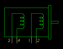
Bipolar motors are the strongest type of stepper motor. You identify them by counting the leads - there should be four or eight. They have two coils inside, and stepping the motor round is achieved by energising the coils and changing the direction of the current within those coils. This requires more complex electronics than a unipolar motor, so we use a special driver chip to take care of all that for us. Some designs (the eight-wire ones) split each coil in the middle so you can wire the motor either as bipolar (short the middles) or unipolar (short the middles and treat the link as the centre tap - see below).
Unipolar
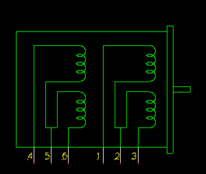
Unipolar motors also have two coils, but each one has a centre tap. They are readily recognizable because they have 5, 6 or even 8 leads. It is possible to drive 6 or 8 lead unipolar motors as bipolar motors if you ignore the centre tap wires. A 5 lead motor has both centre taps connected, so re-wiring them to a 4 lead version requires at least opening the motor, if it can be done at all.
The main beauty of unipolar motors is that you can step them without having to reverse the direction of current in any coil, which makes the electronics simpler. Some early RepRap prototypes used this trick. Because the centre tap is used to energise only half of each coil at a time, unipolar motors generally have less torque than bipolar motors.
Holding torque
Stepper motors do not offer as much torque or holding force as comparable DC servo motors or DC gear motors. Their advantage over these motors is one of positional control. Whereas DC motors require a closed loop feedback mechanism, as well as support circuitry to drive them, a stepper motor has positional control by its nature of rotation via fractional increments.
The Mendel officially requires approximately 13.7 N·cm torque (19.4 ozf·in) of holding torque (or more) for each of the X, Y and Z axis motors to avoid issues, although one stepper with less has been used successfully (see below). Recent designs for extruders (ExtruderController) almost exclusively require stepper motors as well, but no torque requirements have been given in those designs. If in doubt, higher is better.
For Wade's Geared Extruder (most widely used one as of 2012) it is suggested to use motor that is capable of creating a holding torque of at least 40 N·cm.
If you need to convert between different units for the torque you can use the torque unit converter.
In September 2013, Willy did a comparison of a number of commonly used NEMA17 steppers and their torque at various speeds.
Size
The physical size of stepper motors are usually described via a US-based NEMA standard, which describes the bolt-up pattern and shaft diameter. In addition to the NEMA size rating, stepper motors are also rated by the depth of the motor in mm. Typically, the power of a motor is proportional to the physical size of the motor.
If using the smaller NEMA 14 motors, aim for the high torque option. NEMA 14s are neater, lighter and smaller, but can be hard to obtain with the appropriate holding torque. NEMA 17s are quite easy to get in the specification that Mendel needs, but are bulkier and less neat. NEMA 14s are running near the edge of their envelope: they will get warm. NEMA 17s are well inside what they can do, and will run much cooler.
NEMA
- main: NEMA Motor
Refers to the frame size of the motor as standardized by the US National Electrical Manufacturers Association in its Publication ICS 16-2001. It specifies the 'face' size of the motor but not its length. For example a NEMA 23 stepper has a face of 2.3 x 2.3 inches with screw holes to match. Note: just because a motor is bigger does not mean it is more powerful in terms of torque. It is perfectly possible for a NEMA 14 to 'out pull' a NEMA 17 or a NEMA 23.
Based upon the NEMA 17 specification (from what I can find) the mounting holes are spaced 31 mm (1.22 inch) apart along the edge of the motor. This should help if you are using second-hand/salvaged parts.
Shaft
Any part that goes on a stepper motor shaft expects the shaft to be roughly Ø 5 mm. If the shaft is a different size, you will need to make allowances for this in the (plastic) parts you obtain/make.
Wiring
Steppers motors come in several wiring configurations. It is fairly common to find 4, 6 and 8 wires, and these work fine with the standard RepRap electronics. Stepper motors with 5 wires exist but won't work with the standard RepRap electronics, because the 5th wire connects to both coil centers. See stepper wiring for more details.
Heat
Most of the motors specs give the current for two coils that will give an 80 °C rise, i.e. they can run at 100 °C! When using them on plastic brackets you need to under-run them to keep the brackets from melting. With PLA's glass transition temperature between 60-65 °C, you have to seriously under-run them! Fortunately temperature rise is proportional to power, which is in turn proportional to the square of current (P=I2R), but torque is directly proportional so you can keep temperature under control without losing too much torque. For example, running a stepper at 70% of the rated current would result 70% of the torque and 49% (0.72=0.49) of the power dissipation and thermal rise.
Power and current
All recent stepper controllers use a current-limiting design. Because of this, the resistance (ohms, Ω) of the coils doesn't matter, as long as it is low enough for the current to rise fast enough for the current-limiting design to come into play. If the resistance is too high (i.e. 24 V steppers) the current simply doesn't raise enough. For this reason, stepper motors rated for 3-5 V and 1-1.5 A are generally recommended, as these motors will perform near their peak torque with a current-limiting stepper controller (such as a Pololu A4988).
Designs which use a separate "extruder controller board" sometimes use H-bridges (which are designed for running a DC motor) instead of a proper current-limiting stepper controller. On these boards, you need to be careful not to turn the current (PWM) too high, especially with low-ohm (low voltage) motors. You run the risk of overheating both the stepper motor and the H-bridge chip.
Getting and using your stepper motors
Purchasing a motor
The following are unscientific rules of thumb for purchasing the right motor:
- Generally, the longer the motor body, the more torque the motor has.
- If a motor is rated to more amps or volts than your driver can produce, your motor will not produce the manufacturer's rated torque.
- A motor can safely exceed its rated voltage with a chopping stepper driver (which is all the RepRap stepper drivers, save only the Gen3 electronics extruder board hack). A motor that exceeds its rated current (amps) will severely overheat and die a quick death.
- Stepper motors are generally rated for a 50 °C temperature rise at rated current/torque.
- ABS melts at 105-120 °C but softens at 80 °C. Therefore you probably can't run your steppers at their full rated torque without melting your plastic motor mounts.
- Power is measured in watts (W) and is calculated as volts (V) × current (A).
- Power made available to a motor will be turned into heat and motion.
- The more power made available to the motor the higher the amount of heat and motion. Heat is proportional to current squared while motion is proportional to current, so losing a little motion (torque) can lose a lot of heat.
- Current and torque are related. The more current, the more torque. More current also means more power requirement and more heat on motor and stepper driver.
- A motor's rated amps, volts, or ohms (if missing from the spec sheet) can be calculated with the other two numbers using Ohm's law. Or you can cheat and use a calculator.
Does the rule of thumb at Massmind: Estimating Stepper Motor Size work for RepRaps/RepStraps?
Models
The different stepper motor models can be found on their respective pages:
- NEMA 08 Stepper motor
- NEMA 11 Stepper motor
- NEMA 14 Stepper motor
- NEMA 17 Stepper motor
- NEMA 23 Stepper motor
Discovering unknown motors
For starters, see what Traumflug wrote in the forum (in german).
Driving stepper motors
To control your stepper motor, you'll need a stepper motor driver.
Wiring Your Stepper
See Stepper wiring.
Electro-mechanical linear actuators
As an alternative, rather than the motor spinning the lead screw as in most CNC designs, a linear actuator spins an internal lead nut. This pulls the motor up and down a stationary lead screw that passes all the way through the motor. The electronics works identically to other stepper motors - standard stepper motor electronics can drive it. One RepRap researcher points out that this makes the mechanics simpler and, with a few changes to the design, could potentially lower total cost of a RepRap. See First tests of the Haydon linear actuator stepper motor[1][2] by Forrest Higgs.
History
Darwin (RepRap v1.0)
The RepRap Darwin used a NEMA 23 stepper motor. This stepper motor was a unipolar stepper motor which could be configured as a bipolar. This design used 3 stepper motors, one for each axis, and a DC motor for its extruder. Later many people upgraded their extruders to increase their control of the extruder.
Note the Generation 2 electronics supported the first configuration with 3 stepper driver circuit boards for the steppers and a PWM circuit board to control the DC motor.
The Darwin stepper motor requirements were as follows:
| Parameter | Specification |
|---|---|
| Size | NEMA 23 |
| Type | Bipolar |
| Shaft | Dual-output shaft |
| Torque | 71 N·cm (100 oz·in) |
| Resistance | about 10 Ω, or 1 to 30 Ω |
Note: If you are using the PIC controller (Note: Generation 1 electronics) you need a motor that will use about 1A per winding at 12V - that is, around 10 ohms. The Arduino circuit can be adjusted to accommodate a wider range of steppers, but remember that if you specify a low-resistance one and the Arduino controller has to chop the voltage to limit the current going through it, that will also limit the torque.
Comments: Nema23 stepper motor is NOT the best choice for Darwin or other reprap strong 3d printers if you use a 2A stepper driver. At least 24V power supply for a Nema23 stepper and a strong stepper driver up to 3A or 4A are ideal. So if you use 12V and a stepper driver within 2A drive ability, a Nema17 long body stepper motor is recommend or a geared stepper motor is good. A Nema17 60mm stepper motor can have 0.65N.m holding torque. In the other side, a Nema17 60mm stepper motor is much cheaper than a Nema23 stepper or a geared nema17 stepper motor. --Robotdigg 03:47, 30 July 2013
Comment to the comment: NEMA23 steppers work at 12 V just as fine as NEMA17 ones. The bigger diameter results in more torque at the cost of some speed. Speed is rarely a limitation on belt driven drives. --Traumflug 06:26, 30 July 2013 (UTC)
Mendel (RepRap v2.0)
The RepRap Mendel used either NEMA 17 or NEMA 14 bipolar stepper motors. It used four stepper motors: one for each of the three axes and one for the extruder.
Note this configuration of four stepper motors was supported by the 3rd generation electronics.
The Mendel stepper motor requirements were as follows:
| Parameter | Specification |
|---|---|
| Size | NEMA 17 or 14 (prototype was NEMA 14) |
| Type | Bipolar |
| Shaft | Dual-output shaft (need to make knurling the stepper shaft easier, not applicable to recent geared extruders) |
| Torque | 13.7 N·cm (19.4 oz·in) |
| Resistance | Must be over 6 Ω (not applicable to recent stepper controllers, see Power and current above) |
Further reading
- Stepper motor driver
- Motor control loop
- NEMA_17_Stepper_motor
- Printed stepper motors
- Choosing_stepper_for_a_delta
- [3] Some details about steppers and driver electronics


