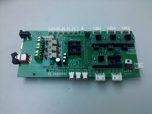
Ultimaker's v1.5.4 PCB
Release status: unknown
| Description | A 5 axis RepRap ArduinoMega Pololu Shield
|
| License | |
| Author | |
| Contributors | |
| Based-on | |
| Categories | |
| CAD Models | |
| External Link |
| FILE ID# | TYPE | DESCRIPTION | AVAILABLE FORMATS | CREATED/RESERVED BY |
|---|---|---|---|---|
| Arduino MEGA Ultimaker Shield v1.5.4.brd | Eagle CAD files | These are Eagle CAD files for the PCB layout | media:Arduino MEGA Ultimaker Shield v1.5.4.brd | --Erik Tue Feb 15 04:00 CET 2011 |
| Arduino_MEGA Ultimaker Shield_v1.5.4.sch | Eagle CAD files | These are Eagle CAD files for the electric circuit | media:Arduino_MEGA_Ultimaker_Shield_v1.5.4.sch | --Erik Tue Feb 15 04:00 CET 2011 |
| Arduino_MEGA Ultimaker Shield_v1.5.4-partslist.xls | Eagle CAD files | These are Eagle CAD files for the electric circuit | media:Arduino_MEGA_Ultimaker_Shield_v1.5.4-partslist.xls | --Erik Tue Feb 15 04:00 CET 2011 |
Version 1.5.4 of the electronics
Warning: this is for version 1.5.4 of the Ultimaker PCB. If you have a older version of this board, this guide does NOT apply.
This is a board that's very similar to other Pololu-based electronics implementations, including RAMPS, but it can support up to 5 steppers (three for X, Y, Z, one for an extruder and one for any other function). You can add as many stepper driver carriers as you need. It is designed to run at higher voltages than 12 Volts, This allows you to put 90 Watts out of one MOSFET and run your stepper motors with more torque and higher maximum speeds. This board is also used on the Mantis-30 milling machine from Protospace and on various Mendel's that people have built.
Specifications
- Arduino Mega Shield
- Plug in all motors with simple 4-way JST connectors.
- Made for Ultimaker's UltiStepper Driver.
- Compatible with Pololu stepper driver boards.
- Controls up to 5 stepper motors (3 for the X, Y and Z axis one for an extruder (the "E axis"), optionally you can add another axis by adding a Pololu stepper driver.
- Configurable step sizes by placing jumpers
- 3x 55 Amp MOSFETs outputs (with LED indicators. Actual current capability limited by PCB and connectors)
- All pins are broken out for maximum extensibility
- Runs from 15V to 19V.
- Three thermocouple inputs, or thermistor inputs. The 100K thermistor is recommended.
- Has a IDC header for adding an LCD panel (movie here)
- Has a header for adding an SD card module.
New features and improvements of previous version:
- A toggle-switch for powering up/down the board
- Easier to wire up thermocouples
- Includes a 12V regulator for an (always on) fan to cool the electronics.
- A PWM output with power for LED arrays and other lighting
- LCD backlight dimming can now be software controlled
- A serial I/O header for bluetooth and ethernet add-ons.
- Servo outputs for experimental setups. They need to be interrupt or software driven as the pins routed to the servo header I/O do not have PWM.
Please provide your comments for further improvements ( erik at ultimaker (dot) c o m ).
Pinout of Extension connectors
Arduino pins as seen from above, the gray box with the text is also the orientation part of the connector
| EXP1 | ||||
|---|---|---|---|---|
| GND | 5 (PWM) | 16 (TX2) | 17 (RX2) | 18 (TX1) |
| 5V | 6 (PWM) | 21 (SCL) | 20 (SDA) | 19 (RX1) |
| EXP2 | ||||
|---|---|---|---|---|
| GND | 38 | 40 | 42 | 50 MISO |
| 5V | 3.3V | 51 MOSI | 53 SS | 52 SCK |
| EXP3 PWM | |||||||
|---|---|---|---|---|---|---|---|
| 5V | GND | 13 | 12 | 11 | 10 | 9 | 8 |
| EXP4 - Unmarked Analog | |||||||
|---|---|---|---|---|---|---|---|
| A12 (Digital 66) | A14 (Digital 68) | A13 (Digital 67) | A15 (Digital 69) | 5V | GND | ||
| Analog | ||||||||||||
|---|---|---|---|---|---|---|---|---|---|---|---|---|
| 3.3V | 5V | GND | GND | VIN (Arduino supply) | A0 (Digital 54) | A1 (Digital 55) | A2 (Digital 56) | A3 (Digital 57) | A4 (Digital 58) | A5 (Digital 59) | A6 (Digital 60) | A7 (Digital 61) |
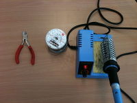
The tools you need
- soldering iron
- solder
- wire-snip pliers
- small hacksaw
Step 1 Solder the arduino-side headers
Double-check if this is the 1.5.3 version of your board.
We start at the back, the side without any text, with the male pinheads.
This will be the base where the arduino will be sitting later. Carefully break or cut the header pins to size.
The best way to get the pins well-aligned, is to put these (with the longest side) in the Arduino, and then the arduino with the pins still sticking out in the backside of the PCB.
This will make sure that the pins are aligned correctly with the Arduino.
Solder the pins on the front side of the PCB, and remove the Arduino afterwards.
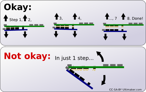
Take care to remove it vertically by alternating between lifting the left and right side of the PCB. You will bend the header pins if you remove it and it finally releases with a twisting motion, see the picture:
When you're done, it should look like this: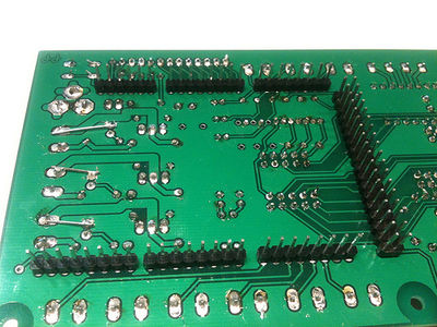
Now we are going to place the components on printed side (with the white silk-screened texts on it). It is good practice to start with the smallest or lowest components.
Add-ons
Thermocouple sensor board
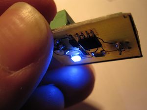
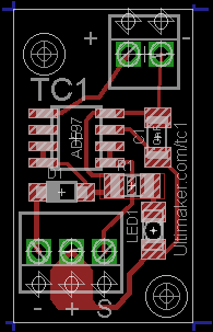
When you have played a lot with DIY 3D printers, you'll find that an accurate temperature measurement of your extruder is very important to achieving the best result. Thermocouples are more reliable and more accurate sensors than thermistors, but the also are more pricey because you need to have the measured signal amplified with a special chip. This chip (in this case AD597) is on the tiny Ultimaker TC board.
Using it with the v1.5.4 PCB
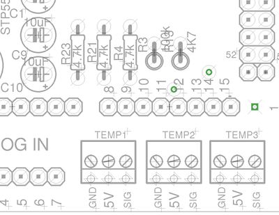
Note: it is very important that the resistor R23 is NOT mounted. The resistor R23 is meant for use with a thermistor based measurement only! If it IS installed, you can just cut it away, because if you have a thermocouple it is unlikely that you will go back to thermistors. Similarly, if you use the other thermocouple inputs (Temp2 or Temp3) you need to leave out resistors R21 or R4 (which are all located next to R23).
The convention for the first extruder, is to use Temp1. In case you use a second extruder, use Temp2 and for a heated bed, use Temp3.
Note: follow this specific order:
- Connect the 5V to the thermocouple board.
- Power up the Arduino by connecting it to the USB port of your computer.
- Connect the ground (- or GND) to the thermocouple board. The blue LED should light up on the little thermocouple board.
- If you already have the software installed: Open up ReplicatorG, look at what reading you get in the control panel.
- Connect the signal wire (Sig). See if the value changes. If it does not, you have the wires connected incorrectly or the firmware tries to read a different input.
The thermocouple board has three connections to the Ultimaker PCB, signal, power (+ or 5V) and ground (- or GND). The preferred wire colors are brown or any other color, red and black, respectively.
The Ultimaker thermocouples have Yellow and Red wires. The yellow one goes into the + of the little thermocouple sensor board, the red thermocouple wire goes into - of the thermocouple board (on the TWO wire screw terminal, not the 3 wire terminal). Cut the thermocouple wire to exactly 15 centimeters, this is optimal because the wire will pick up less interference (the shorter the better) but not be too short (which is a problem for the sensor chip, it thinks the inputs are shorted out).
Checklist / What to do if it doesn't work
- Always make sure you're running the Ultimaker firmware.
- The temperature goes DOWN to 0 if I heat up the thermocouple. This means that you have switch the thermocouple wires.
- The values are incorrect: Check if the resistors are left out or removed (see above).
- The value is 499.9 degrees: Check if all connections are correct, and if reliable wires are used.
- Does the temperature fluctuate too much? Check if C1, C9 and C10 are installed.
- The thermocouple is nothing more that two wires of a specific metal that are connected together at one end. This is the measurement end. You can make your own by fusing the end together (do not use solder, it will melt at normal operating temperatures of the extruder. The original thermocouple supplied with Ultimakers has a standardized thermal resistance to the aluminium heater block, so this will give the most reliable measurement.
- Using your own firmware? The AD597, as used in the Ultimaker thermocouple PCB, is fully compatible with the AD595. Make sure that the AD595_THERMOCOUPLE is defined and thermistor measurements are turned off.
- If you switched the black and signal wires, the LED can be lit, but this is no confirmation that you've wired it up correctly. Incorrect wiring may damage your thermocouple sensor board.
- The thermocouple always shows room temperature, but isn't changing when I warm up the thermocouple with a lighter: the AD597 chip is currently in self-measurement mode. If the + and - inputs of the thermocouple have a very low resistance, it will not give you the temperature of the thermocouple, but of the chip itself. Check this by placing a warm finger on the chip. If the value change quickly, this is indeed the case. Extend the thermocouple wires with terminal blocks or solder them together to get a higher resistance between the thermocouple inputs.
Prototype / Design
Picture: CC-SA-BY Erik de Bruijn
Files:
- File:Thermocouple board v0.4.sch - files are licenced Creative Commons, Attribution, Share Alike
- File:Thermocouple board v0.4.brd - files are licenced Creative Commons, Attribution, Share Alike
LCD
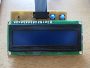
The configuration of the LCD with buttons is explained on the Ultimaker wiki (thanks to Bernhard!).
This is an add-on board for Hitachi parallel interface LCD controllers. . Currently the firmware uses two lines of 16 characters on the display.SD-CARD and Micro SD-CARD
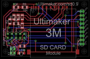
Erik developed a SD-CARD expansion. This add-on also has a led and a break-out of all the used pins.
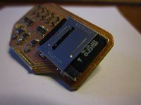
Jan-Jaap also developed a micro SD-card expansion which is a bit smaller, it does includes a led but doesn't included the pins break-out.
It is documented on his blog:
http://jjshortcut.wordpress.com/2011/03/28/ultimaker-mirco-sd-card-extension/
Wireless/Bluetooth
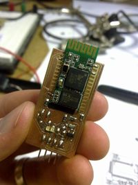
Jan-Jaap developed a bluetooth add on that allows for wireless printing.
It is documented on his blog:
http://jjshortcut.wordpress.com/2011/02/19/wireless-serial-bluetooth-module/
| FILE ID# | TYPE | DESCRIPTION | AVAILABLE FORMATS | CREATED/RESERVED BY |
|---|---|---|---|---|
| Ultimaker SD Add-on v0.9 for v1.5.4.sch | Eagle CAD files | These are Eagle CAD files for the electric circuit | media:Ultimaker_SD_Add-on_v0.9_for_v1.5.4.sch | --Erik Tue Feb 15 04:00 CET 2011 |
| Ultimaker SD Add-on v0.9 for v1.5.4.brd | Eagle CAD files | These are Eagle CAD files for the PCB layout | media:Ultimaker_SD_Add-on_v0.9_for_v1.5.4.brd | --Erik Tue Feb 15 04:00 CET 2011 |
Changes
- There was a tiny mistake in the silkscreen, the 36 pin header of the Arduino has 5V on pins 1 and 2 and GND on pins 35 and 36. The mistake is that the silkscreen has a label for Arduino digital pin 22 and 23 one row too high (so besides the 5V outputs). Since version 1.5.4 this is fixed.
- 1.5.4 can measure if the power it turned on and which voltage power supply was connected.
- Please let us know if you find errors!
