User:Wayland

I'm going to use this page as sort of a documentation for my repstrap. It'll be cheap, as much as I can make it. It probably won't have a great print area for its size (but it's pretty freaking huge), but I don't need to keep this thing on a desk. Y axis runs on aluminum channel, X axis will run on steel rod, and z axis is on threaded rod, with the print platform moving. I'm thinking about using pololu stepper drivers and the sanguino for a motherboard. For the extruder, I might use Adrian's geared extruder, if I can get someone to print the parts for me...
Current Progress: I need a belt for the z-axis and have contacted some friendly people who might make me some pulleys. Also I'm about to order things.
To Do List (Not really in order)
(things will be listed as they are foreseen, stricken out when they are completed, and deleted when they are documented and photographed.
- Obtain timing pulleys and belt and finish z-axis
-
Cut print platform from plexiglass, drill holes, and epoxy nuts onto it. - Build x-axis
- Build belt drive system for x and y axes
- Buy stuff (see below)
- Sell reprap parts to recover whatever money I'll have sunk into this and buy more plastic and fund some other projects.
- Give away free parts?
Parts
I have basically a scrapyard in my backyard, so a lot of these parts are salvaged. This is a prety cobbled-together thing.
- Aluminum plate, channel, and angle - Salvaged, cut to size with circular saw, drilled with drill press
- 3 Stepper motors - Cheap surplus-store Molon steppers (these guys) - Almost no specifications, I will test them and figure out voltage and current once I get my power supply and drivers. They don't have a great resolution - I'm thinking I will gear them. If they're no good, I can always buy some NEMA 17s.
- 8 skate bearings - Salvaged from an old generic-brand skateboard. These are pretty nice bearings and perfect for what I have in mind. These are just for the y axis - I'm gonna need to find or buy some more for the carriage.
- Threaded rod - Salavaged. I really don't know what these are from, we just had them lying around. As a side note, if you ever come across old free car seats, look under them. The ones I've seen have pretty nice threaded rod with little things on them - basically my z-axis, but already assembled. Just find two car seats and you're set!
To buy list:
- 4x Pololu Stepper Drivers
- Sanguino/Seeduino/Arduino (feel free to weigh in on this)
- PWM, thermistor, nichrome wire, PTFE insulator, m6 nut, basically all the extruder things.
- Opto Endstops (probably from makerbot)
- Stepper motor for extruder, depending on which extruder I get printed
- Belt
- PLA!
Links I don't want to lose:
- http://www.nkcelectronics.com/seeeduino-mega-fully-assembled.html - $40 seeduino mega!
- http://www.moderndevice.com/products/sanguino - or should I get a $35 complete sanguino? Hm...
- http://ultimachine.com/content/31ga-nichrome-wire - cheap nichrome wire. they also have some nice PLA for cheap and PTFE thermal barriers
Y-Axis

I really liked the self-adjusting bearing arms used in the McWire Cartesian bot, so I made something similar; instead of using a platform, though, I'm using separate (for now) carts that will have the x-axis running between them. There will be belt going through the middle of this thing moving it. It's kind of hard to explain.

The cart is made of sheet aluminum , as are the bearing arms. The fixed bolts have on them: a spacer, the bearing arm, the bearing, and the nut. The floating bolts are just the arm, bearing and nut. There is a small hole on the inside of each bearing arm; I had planned to use springs like in the McWire, but I only had rubber bands around to test it with, which ended up working fine. If the rubber bands break, though, I'll switch. I ended up switching the rubber bands out for extension springs because they sort of lost their tension. Works great, now.
These carts run on a frame I made from aluminum channel.

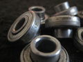
Salvaged skate bearings
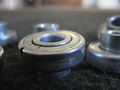
More bearings
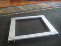
Aluminum channel frame
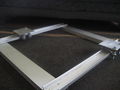
Frame with carts


Z-Axis
The z-axis runs on four threaded rods arranged vertically in the frame's corners. There are holes in the corners of the x-y frame which the threaded rods go through, and, over the hole, is a washer and a bearing to lessen friction. On the bottom of the legs are guides to keep the threaded rod straight and more bearings. A stepper will be powering one threaded rod, which will then power the rest of them via pulleys and a timing belt. The stepper shaft will be joined to the threaded rod with a short length of neoprene tubing, similar to the mcwire. I will attach it as soon as I assemble the platform and pulleys.