File:SAV MkI Connection diagram.png
Revision as of 15:41, 15 May 2014 by Fmalpartida (talk | contribs) (Fmalpartida uploaded a new version of "File:SAV MkI Connection diagram.png": Corrected typo in 12V auxiliary rail polarity.)

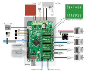
Size of this preview: 739 × 600 pixels. Other resolutions: 296 × 240 pixels | 1,024 × 831 pixels.
Original file (1,024 × 831 pixels, file size: 757 KB, MIME type: image/png)
File history
Click on a date/time to view the file as it appeared at that time.
| Date/Time | Thumbnail | Dimensions | User | Comment | |
|---|---|---|---|---|---|
| current | 08:07, 27 December 2014 | | 1,024 × 831 (757 KB) | Fmalpartida (talk | contribs) | Added inductive sensor. |
| 13:55, 19 October 2014 | 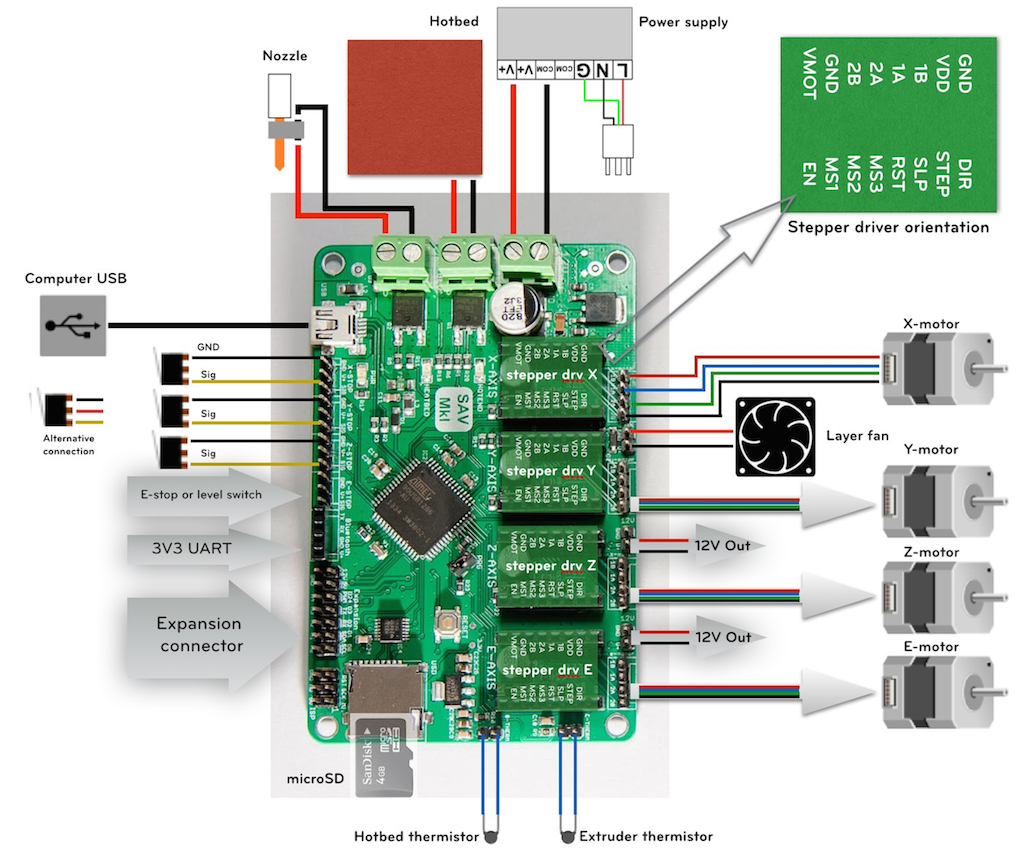 | 1,024 × 854 (908 KB) | Fmalpartida (talk | contribs) | Added connection switches. | |
| 15:41, 15 May 2014 |  | 1,944 × 1,628 (1.82 MB) | Fmalpartida (talk | contribs) | Corrected typo in 12V auxiliary rail polarity. | |
| 19:07, 2 May 2014 |  | 2,018 × 1,502 (1.51 MB) | Fmalpartida (talk | contribs) | Corrected errata in connection diagram where the hotbed and hot end were exchanged. | |
| 17:19, 13 April 2014 |  | 2,092 × 1,760 (2.07 MB) | Fmalpartida (talk | contribs) |
- You cannot overwrite this file.
File usage
The following 3 pages link to this file: