Generation 3 Electronics/Tech Zone Remix/How to
I'm writing as a manual to the "TechZone Electronics Kit"... Please feel free to edit any errors or discrepancies... feel free to add to this page...
This page (as of now) is purposely not linked inside the wiki... (the ground-work needs to be laid-out first and pics need to be uploaded... so here we go...
Contents
- 1 Befor We Begin... Things You Should Know...
- 2 The USB/TTL Board
- 3 The Main Motherboard
- 4 The Extruder Board
- 5 The Stepper Board
- 6 The Opto End-stop
Befor We Begin... Things You Should Know...
First: (Kiymberly, Here's your cue!!! this parts all YOU!)
389483rd... The TechZone electronics kit comes with Makerbot firmware by default! This means that the ReprepMendel firmware needs to be uploaded to the motherboard and extruder-board to pre-configure them before you start connecting/testing them...
The USB/TTL Board
To begin we need to clearly mark the ground pin of the serial connection... (here we need a pic of the board pointing out the ground pin and marking it with a sharpie...)
Drivers
I have tried 3 Diffrent sets of (Windows) USB/TTL drivers and all seem to work fine... The drivers I tried are as follows:
1. The drivers that come bundled with replecatorG
2. The drivers that come bundled with Reprap Host Software
3. The drivers off the IC Manufacture's website
The Main Motherboard
text (here we need a pic of the mother board labeling the pins... by needed connections..(connetions that apply to reprap mendel)
Connecting The Motherboard to the USB/TTL board to Load Firmware
Making the Connection
Making Your Cables (Insulation Displacement Connectors)
text
The Jumper Technique...
This is a solution I came up with to upload the needed firmware for setup, bench testing and for troubleshooting cable problems... As you can see from the pictures below I used reversible jumpers that I pulled from old computer parts. *Note if you use this technique on the extruder board, you will need to flip the USB/TTY board up-side-down... due to the fact that the ground pin on the extruder board is on the opposite side!
Uploading Firmware
Once you have connected your USB/TTL interface to your motherboard you can upload the Motherboard 5Gfirmware for the first-time!!!
The processes of uploading firmware are the same as the Makerbot set... The only diffrence is that the jumper to upload firmware is already installed... Microcontroller_firmware_installation
The Extruder Board
text
Uploading Firmware
Jumpers Again? Yep
- Note if you use this technique on the extruder board, you will need to flip the USB/TTY board up-side-down... due to the fact that the ground pin on the extruder board is on the opposite side!
Making the Connection
12 Volt power
Rs485 Connection
Step/Direction Connection (SDA/SCL)
Cooling
Stepper Motor Connection
CD-Rom Audio Cable Technique
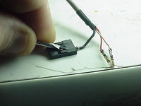
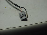
What i did was i used a cd-rom analog audio cable for my i2c signal... using a small screw driver, i was able to remove the pins from the connectors and re-arranged them to my needs leaving the ground pins loose so i could connect them to the ground pins on the boards...
The Stepper Board
text
Making the Connection
Connecting Your Stepper Motor
Connecting power 12 Volt power
Here are a few ways to make a 10 pin cable...
Making a 10pin IDC Cable
Some things on this topic have already been covered...Electronic_wiring#Stepper_wiring
Make 2 out of an IDE cable
Taking a IDE cable from a computer, I was able to Make 2 10pin ribbon cables using a hack saw... by cutting the connector almost all the way through with the saw I was able to achive a clean break through the last bit of plastic close to the cable. (PIC PIC PIC)
Make a breakout to use a Stepper Board to drive your Stepper Extruder Motor... (optional Stepper board needed)
Comming soon!
The Opto End-stop
text


