RAMPS 1.7
|
English • العربية • български • català • čeština • Deutsch • Ελληνικά • español • فارسی • français • hrvatski • magyar • italiano • română • 日本語 • 한국어 • lietuvių • Nederlands • norsk • polski • português • русский • Türkçe • українська • 中文(中国大陆) • 中文(台灣) • עברית • azərbaycanca • |
Release status: Prototype

| Description | RepRap Arduino Mega Pololu Shield
Arduino MEGA based modular RepRap electronics.
|
| License | |
| Author | |
| Contributors | |
| Based-on | |
| Categories | |
| CAD Models | |
| External Link |
Contents
Summary
I am working on developing a RAMPS version that will allow TMC2130 drivers (using SPI) to be used, simply by moving some jumpers.
This is a link to a forums discussion about the board
The board is also meant to be usable with 32-bit processors that use 3V logic, like the Arduino DUE
PCB
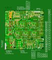
Latest version
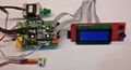
Test using Due
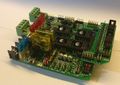
Assembled test board


Click any image for larger versions
Sources
Firmware
Very preliminary firmware testing
- For Arduino Mega, based on Marlin bugfix-1.1.x for RAMPS_1.7 at GitHub (still uses the 1.4 name and settings, but has 1.7 pin numbers in the pins_RAMPS.h file)
- For Arduino DUE and Mega, based on Marlin bugfix-2.0.x for RAMPS_1.7 at GitHub
Design files
As soon as I know that the design actually works, all files I have/use will be made available.
So far about the PCB RAMPS 1.7 GitHub repository
Schematics
On this wiki the schematics will be made available as images.
For pdf versions see: Repository at GitHub
Heated Bed circuit

Click picture for larger versions.
Link to pdf version on GitHub
"12V" & 5V rails

Click picture for larger versions.
Link to pdf version on GitHub
12V, 8V & 5V on-board power
It is possible to add up to three on-board DC-DC converters. This makes it very simple to add additional 5V power to the board. Or add 12V power (for quiet fans) when using a single 24V power supply.
The MP1584 adjustable DC-DC switch mode regulators fit very nicely into the provided socket positions.
For use with Arduino Mega
The Arduino Mega on-board 5V regulator is known to overheat (causing random resets), if it is also used to power too many 5V add-on items, especially if it is supplied directly from a 12V power supply.
The 8V DC-DC port position is very suitable for the purpose of lowering the heat otherwise dissipated in the Mega 5V linear regulator chip.
If you use a 24V power supply, it can be nice to also have 12V available for (quiet) fans. By using a few jumpers on the RAMPS 1.7 shield, the 12V DC-DC port position on the board, can supply 12V to the four fans ports Fan1-Fan4. You will need to cut a PCB wire if you also want 12V to the Fan0 port.
The spec for the MP1584 DC-DC boards is a max of 3 amp output.
For Use with Arduino DUE
The Arduino DUE has an on-board switch mode regulator for it 5V power rail, and a linear 3.3V regulator tapping of the 5V rail, so the DUE it will not overheat if supplied 12V to Vin. The DUE board does however have a limit of max 16V power in.
So for this reason it is recommended to use the sockets provided on the RAMPS 1.7 board, to add a DC-DC regulator, in the 12V DC-DC port position, if you use a single 24V power supply for your 3D printer.
5V USB power to a RPi
The 5V DC-DC port can be used to power an RPi. The spec for the MP1584 DC-DC board is max 3 amp output.
You will need to cut a Micro USB cable and fit it with a Dupont connector, in order to get 5V from the RAMPS 1.7 board to the RPi.
Illustrations (for 1.7B)

Click picture for larger versions.
Link to pdf version on GitHub
Note the Jumper J2 in right hand corner

Click picture for larger version
Note the Jumper J2 in right hand corner

Click picture for larger version

Click picture for larger version
Once I have adjusted the MP1584 DC-DC regulator to output 5V, I usually hot-glue the trimmer.
Jumpers & Aux-connectors
Stepper driver jumpers


Aux-connectors
Aux-1


Aux-2


Aux-3
Aux-4
Aux-5
Aux - Not numbered
Servo

- S0 - Servo 0
- Arduino pin D4
- Alternative use: none
- S1 - Servo 1
- Arduino pin D5
- Alternative use: none
- S2 - Servo 2
- Arduino pin D6
- Alternative use: With TMC2130 as SPI E1_Chip_Select (E1cs)
- S3 - Servo 3
- Arduino pin D7
- Alternative use: With TMC2130 as E1_Diagnose_1 (E1cf)
Jumpers and options
Bill Of Materials
A (partial) list of components that are used for this board.
| ID | Description | Quantity | Digikey Part Number (Description) | Other supplier | Notes |
|---|---|---|---|---|---|
| C1 | Low ESR 100uF/35V | 6 | PCE4554CT-ND | ? | 6.60mm x 6.60mm |
| C2 | 10uF/35V | 4 | PCE4235CT-ND | ? | 4.30mm x 4.30mm |
| C3 | 1-10uF / 6V / 0805 | 1 | CAP CER 10UF 6.3V X5R 0805 | ebay option | 0805 |
| C6 | 100nF / 6V / 0805 | 11 | CAP CER 0.1UF 50V X7R 0805 | ebay option | 0805 |
| Q3,Q4 | IRLB3034 N-channel mosfet, 2 mili Ohm, 40V |
2 | IRLB3034PBF-ND | ? | TO-220 |
| Q3,Q4 Alternative | IRLB8743 N-channel mosfet, 4 mili Ohm, 30V |
2 | IRLB8743PBF-ND | ? | TO-220 |
| Q1, Q2 | IRLR7843 N-channel mosfet, 4 milli Ohm, 30V |
2 | IRLR7843PBFCT-ND | ? | TO-252 |
| N | AO3400 N-channel mosfet, 33-52 milli Ohm, 30V |
7 | 785-1000-1-ND | ? | SOT-23 |
| IC | 74LS125 | 2 | SN74LS125ADR | ebay option | 14-SOIC (0.154", 3.90mm Width) |
| IC | 24LC256 | 1 | 24LC256 | ebay option | 8-SOIC (0.154", 3.90mm Width) |
| S1 | 4-pin 7.62mm screw terminal | 1 | ?d | ?o | ?n |
| S2 | 2-pin 5.08mm screw terminal | 4 | ?d | ?o | ?n |
| R1 | 100K 0805 | 15 | Digi option | ebay option | 0805 |
| R2 | 10K 0805 | 6 | ?d | ?o | 0805 |
| R3 | 4K7 0805 | 15 | ?d | ?o | 0805 |
| R4 | 2K2 0805 | 11 | ?d | ?o | 0805 |
| R5 | 10R 0805 | 6 | ?d | ?o | 0805 |
| R6 | 1K 0805 | 1 | ?d | ?o | 0805 |
| R7 | 680R 0805 | 1 | ?d | ?o | 0805 |
| R | 20K 0805 | 3 | ?d | ?o | 0805 |
| E1-3 | Green LED 0805 | 3 | ?d | ?o | 0805 |
| E4 | Red LED 0805 | 7 | ?d | ?o | 0805 |
| E5 | Yellow LED 0805 | 1 | ?d | ?o | 0805 |
| D2 | diode TH | 1 | 1655-1921-1-ND | ebay options | Any 6-10A diode will however do fine |
| D1, D3-D5 | diode 1N4007 smd | 4 | DIODE SCHOTTKY 30V 1A DO214AA | ebay options | Housing: DO-214AA / SMB |
| Diode | 1N5819 / S4 - smd | 7 | Digi Options | ebay options | SOD-123 or "DO-213AB, MELF (Glass)"
|
Fuse options
| ID | Description | Quantity | Digikey Part Number (Description) | Other supplier | Notes |
|---|---|---|---|---|---|
| F1,F2,F3 | Auto blade fuse / 1808 | 3 | ?d | ?n | |
| _ | Auto blade fuse sockets | _ | ?d | ebay option 1 ebay option 2 |
?n |
| _ | 1808 socket | _ | ?d | ebay 1808 socket options | ?n |
| _ | 1808 10A fuse | _ | ?d | ebay 1808 10A fuse options | ?n |
| F4-F12 | Is currently a "PCB-wire fuse", it will however not protect the electronics, only the rest of the PCB wire. So far the fuses I have tested have simply been too slow, to be able to protect the AO3400 mosfets, if one would still want a 2A 12V power rail for the fans. So for now, I have opted to at least know where the PCB wire might fry, if a short circuit condition gets out of hand. When a pcb-wire-fuse blows, just replace with a single strand of very thin wire, so the "fuse" part will still be effective. |
? | ?d | ? | ?n |
Pin headers
| ID | Description | Quantity | Digikey Part Number (Description) | Other supplier | Notes |
|---|---|---|---|---|---|
| 2p male | txt | ? | ?d | ?o | ?n |
| 3p male | txt | ? | ?d | ?o | ?n |
| 1 row x 8p female | txt | 10 | ?d | ?o | ?n |
| 1 row x 2p female | txt | 12 | ?d | ?o | ?n |
| 2 row x 2p female | txt | 2 | ?d | ?o | ?n |
| 1 row x 4p female | txt | 1 | ?d | ?o | ?n
|
Board assembly
I always find it easiest to solder in the smallest and lowest components first.
Once all components are soldered to the top, then it is advisable to solder in the pins on the bottom, that connects the shield to the Arduino. Because once the top-pins, jumpers and headers are soldered, it becomes very difficult to reach the solder points for the bottom pins, with the soldering iron, without also melting some of the header plastics.