Mondrian/fr
|
English • العربية • български • català • čeština • Deutsch • Ελληνικά • español • فارسی • français • hrvatski • magyar • italiano • română • 日本語 • 한국어 • lietuvių • Nederlands • norsk • polski • português • русский • Türkçe • українська • 中文(中国大陆) • 中文(台灣) • עברית • azərbaycanca • |

Contents
- 1 Previous versions
- 2 Tools
- 3 General tips
- 4 Step 1/18 - Corners (base)
- 5 Step 2/18 - Base frame
- 6 Step 3/18 - Endstops
- 7 Step 4/18 - Z-sliders
- 8 Step 5/18 - Z-pillars
- 9 Step 6/18 - Z-motor
- 10 Step 7/18 - Z-axis
- 11 Step 8/18 - Bed
- 12 Step 9/18 - Corners (top)
- 13 Step 10/18 - Y-sliders
- 14 Step 11/18 - X-slider
- 15 Step 12/18 - Hotend
- 16 Step 13/18 - Back panel
- 17 Step 14/18 - Wiring
- 18 Step 15/18 - Finishing touches
- 19 Step 16/18 - Driver
- 20 Step 17/18 - Firmware
- 21 Step 18/18 - Software
- 22 Step 19/20 - Bed calibration
- 23 1ère impression
Previous versions
The build manual for the previous versions are here :
Tools
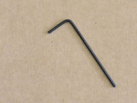
1,5 mm hexagonal wrench (for the pulleys grub screw)
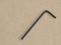
2,0 mm hexagonal wrench (for M3 counterksunk bolts and pneumatic fittings "MA-12-03-M5")

2,5 mm hexagonal wrench (for normal M3 cap-head bolts and the rounded M4 bolts used for the frame)
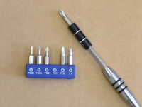
1 cross-head screwdriver (for the PSU screw terminals)
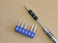
2,0 flat screwdriver (to set the drivers current)
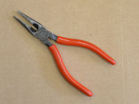
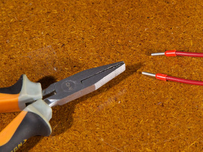
1 flat-nose pliers or 5,5 mm flat spanner (for M3 nuts)
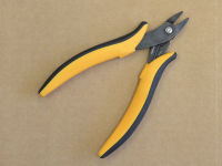
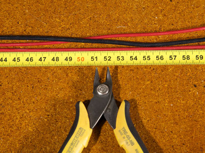
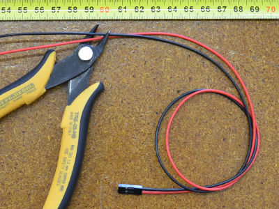
1 cutting pliers and / or automatic striper (to cut the wires and strip them)

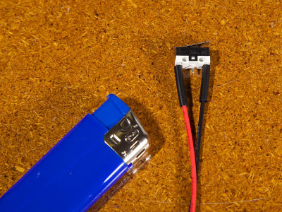
1 lighter (to for the heat-shrink sleeves
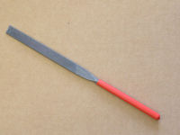
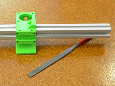
1 file (to adjust the printed parts)
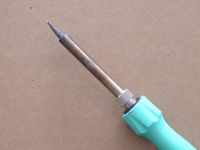
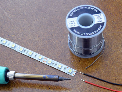
1 soldering iron (for the LEDs strip)
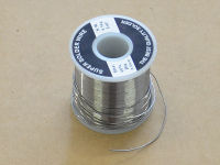
1 solder wire


General tips
<videoflash>oy6gteUXlsY</videoflash>
- Read the whole manual before starting to get an overview of the building steps (total: 12 hours of assembly).
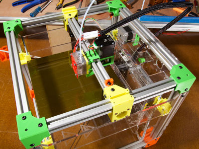
- The FoldaRap is made of a base frame and several sub-assemblies. Some can be done in parallel to save time, gather your friends and establish a new building time record !
- Work on a cutting mat if you have one: it will protect your table plus they often show a millimetre grid that can be useful to check the bolts length (with experience you will recognize them by looking or holding one).
- Place your mouse over a picture to know the element name.
- Do not hesitate to have a look at the 3D model in SketchUp (before/during the build): it will show you the folded/unfolded state of the machine and you can play around with it.
Printed parts

base corner

top corner

z-slider

z-slider (z-endstop)

y-slider left

y-slider right
x-slider
hotend-holder
extruder
belt-end
spool-holder

belt-adjuster
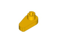
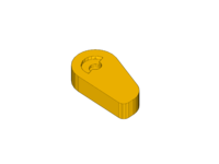
cup
z-endstop
door-lock outer
door-lock inner


Lasercut parts
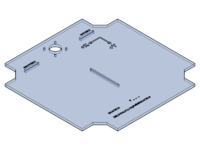
bottom panel

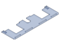
back panel
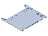
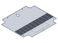
z-axis panel
side panel
electronic cover (1)
electronic cover (2)
door
Insert a T-nut
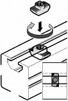
tightening torque: 2.5 N.m (+/- 5%): use the small side of the 2.5 hexagonal wrench to get the ideal torque

Step 1/18 - Corners (base)
 x4 corner-base
 x8 605zz bearing


 x4 pulley
![]() x8 grub screw
x8 grub screw


 x1 closed-loop-belt
 x4 threaded-rod
 x8 M5 washer


Step 2/18 - Base frame
 x4 M4x8
 x4 T-nut
 x4 300mm profile
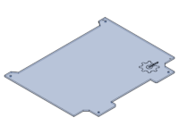
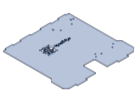
 x1 panel-bottom


x4 M4x8
x4 T-nut
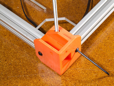

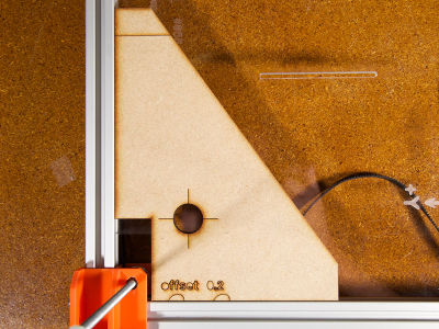
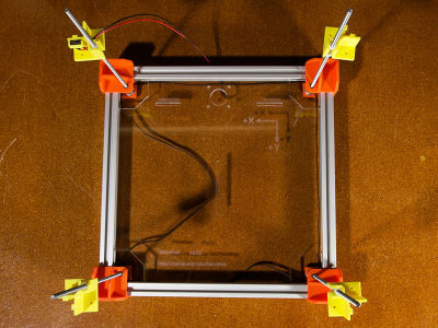
check the perpendicularity of the structure with the pattern and readjust it if necessary


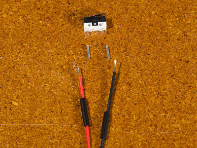
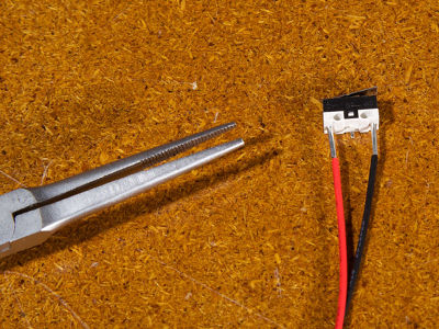
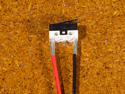
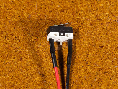
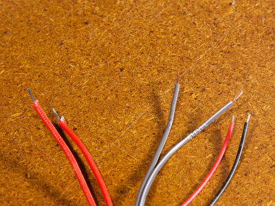
Step 3/18 - Endstops
 x1 heatchrink tubing


X-endstop
 x1 endstop
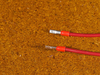
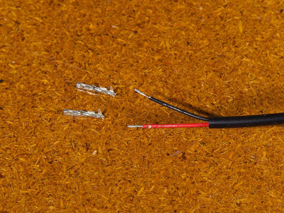
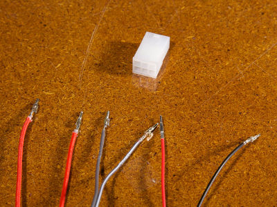
 x2 ferrule
take red/black wires + 2-pin connector


Y-endstop
x1 endstop
x2 ferrule
take red/black wires + 2-pin connector
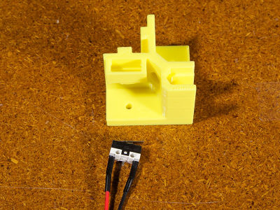
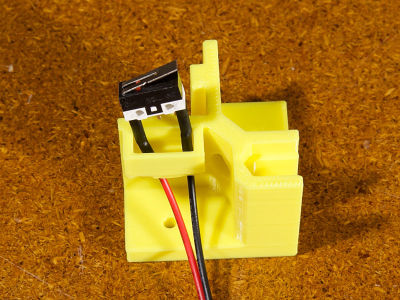
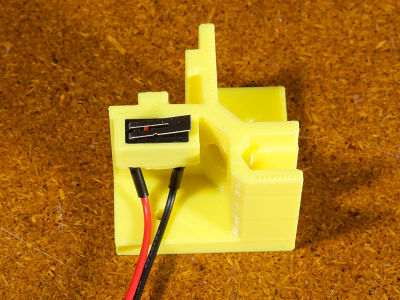
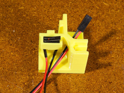
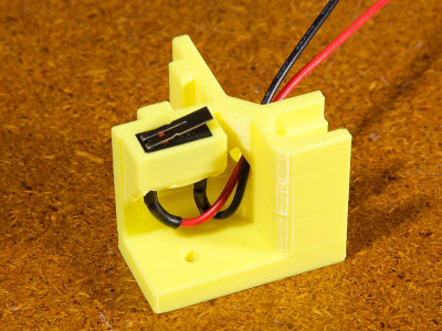
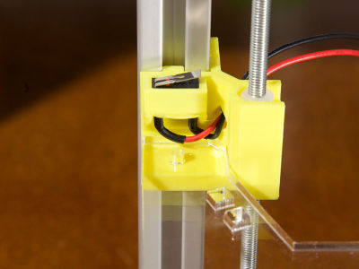
Z-endstop
 x1 z-slider-endstop
x1 endstop
x2 ferrule
x1 z-slider-endstop
x1 endstop
x2 ferrule
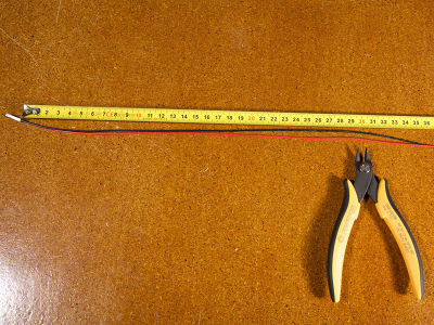
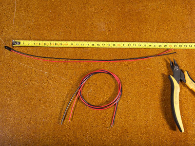
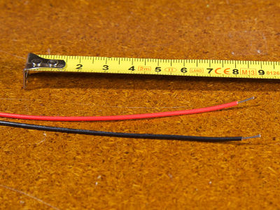
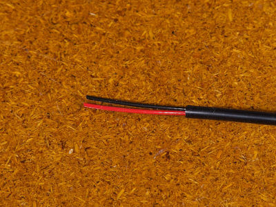
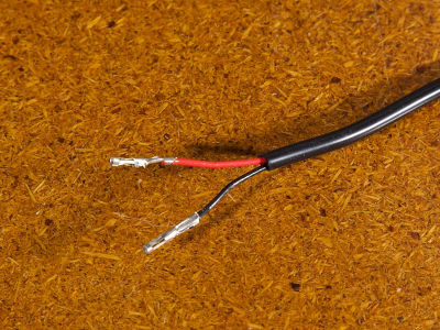
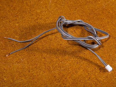
cut 30cm of red/black wires + 2-pin connector
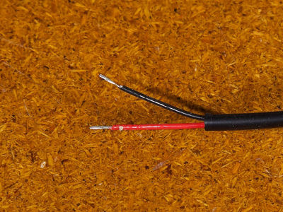
strip the extremities


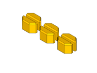
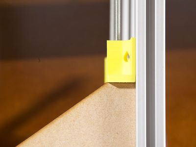
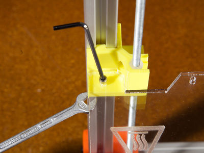
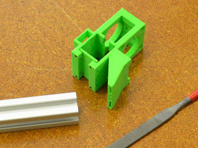
Step 4/18 - Z-sliders
 x3 z-slider
x1 z-slider-endstop
x3 z-slider
x1 z-slider-endstop
 x8 nylon nut
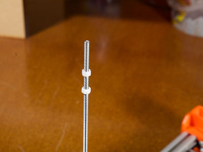
screw the nylon nuts on the threaded rods

place the z-sliders on the nylon nuts: make sure that there is NO PLAY between the nylon nuts and the z-sliders (otherwise adjust the position of the nylon nuts on the threaded rods)


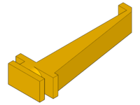
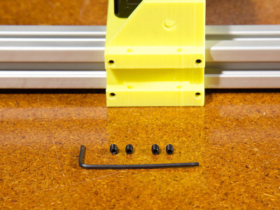
Step 5/18 - Z-pillars
x4 300mm profile
x8 M4x8
x8 T-nut


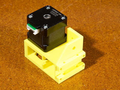
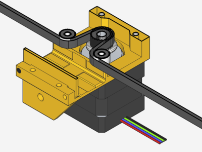
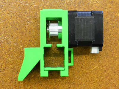
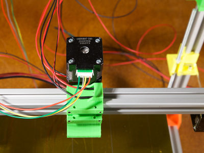
Step 6/18 - Z-motor
Z-motor
 x1 nema 17
x1 pulley
x1 nema 17
x1 pulley
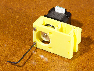
![]() x2 grub screw
x2 grub screw
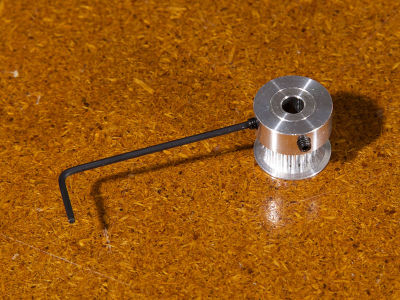
lock the pulley with one grub screw on the flat part of the shaft

fix the motor on the lasercut part (be careful with the connector orientation)


 x2 M3x10
x2 M3 washer
x2 M3x10
x2 M3 washer


 x2 M3x20
x4 M3 washer
x2 M3x20
x4 M3 washer
 x4 roulement 623zz
 x2 M3 washer (large)


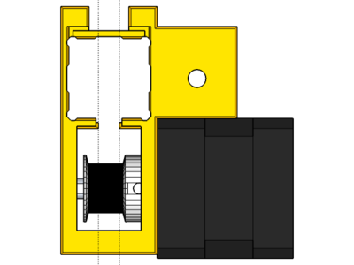
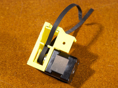
Toothed-wheel
 x1 belt adjuster
 x1 M3 nut
x1 M3x25
x2 roulement 623zz
x2 M3 washer
x2 M3 washer (large)
x1 M3 nut
x1 M3x25
x2 roulement 623zz
x2 M3 washer
x2 M3 washer (large)


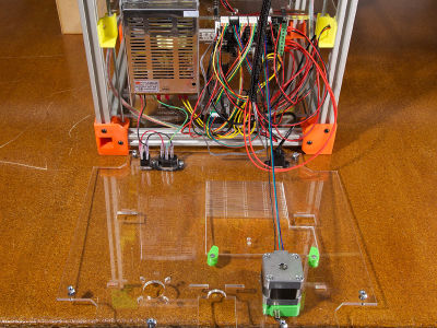
Step 7/18 - Z-axis
 x1 panel-z-axis
 x4 M3x16
x4 M3 nut
x4 M3x16
x4 M3 nut
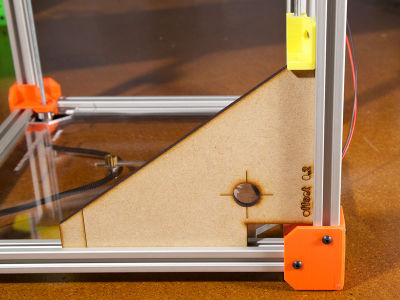
position the 4 z-sliders at the same height thanks to the pattern
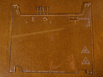
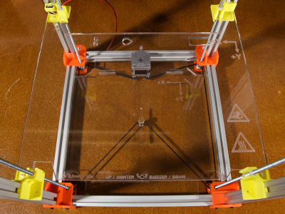


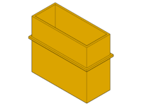
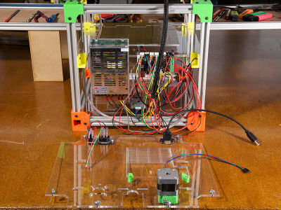
Step 8/18 - Bed
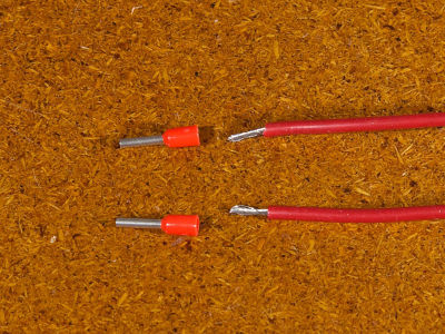
 x2 cable terminal (1.5mm)
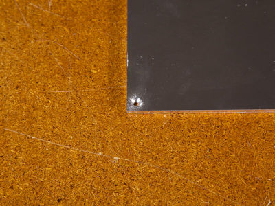
one side of the aluminium bed has countersunk holes...
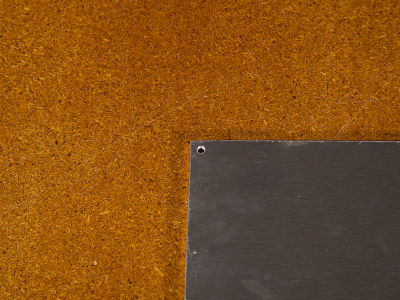
... the other one not... position the bed so that the countersunk holes are against the table
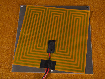
remove the plastic from the film heater and stick the film heater on the aluminium bed like shown on the picture


 x2 2,54mm female ferrule
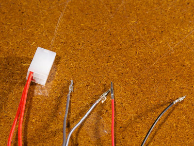
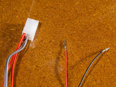
 x1 2-pin casing
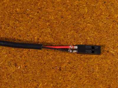
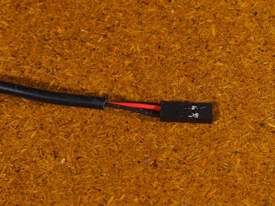
push the ferrules completely in the 2-pin casing


 x3 M3x35 countersunk
x3 M3 nut
x3 M3x35 countersunk
x3 M3 nut
![]() x3 spring
x3 spring
 x3 wingnut


 x2 zip-tie
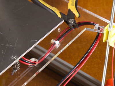
fix the cables on the z-axis panel with zip-ties


Step 9/18 - Corners (top)
 x4 corner-top
x8 M4x8
x8 T-nut
x4 corner-top
x8 M4x8
x8 T-nut


x2 300mm profile
x4 M4x8
x4 T-nut


Step 10/18 - Y-sliders
x1 nema 14
x1 pulley
![]() x2 grub screw
x2 grub screw

 x1 y-slider left
x2 M3x30 countersunk
x1 y-slider left
x2 M3x30 countersunk
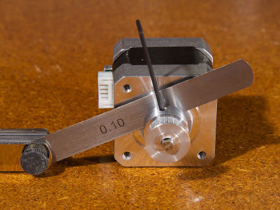
check the alignement of the pulley teeth with the y-slider


 x1 360mm belt
x2 M3x30 countersunk
x2 603zz bearing
x1 360mm belt
x2 M3x30 countersunk
x2 603zz bearing
pass the belt over the pulley...

... and catch it with a M3x30 countersunk...

... and a 603zz bearing...
... on both sides of the y-slider


x1 300mm profile

make sure that the y-slider slides easily without play on the aluminium profile (if not: file a bit the inside part of the printed piece until it slides well)

 x2 x-belt end
x2 M4x8
x2 T-nut
x2 x-belt end
x2 M4x8
x2 T-nut


![]() x4 grub screw
x4 grub screw

if necessary: reduce the play between the printed part and the aluminium profile with the 4 grubscrews


 x1 y-slider right
x1 nema 14
x1 pulley
x1 y-slider right
x1 nema 14
x1 pulley
![]() x6 grub screw
x1 300mm profile
x4 M3x30 countersunk
x2 603zz bearing
x1 360mm belt
x2 x-belt end
x2 M4x8
x2 T-nut
x6 grub screw
x1 300mm profile
x4 M3x30 countersunk
x2 603zz bearing
x1 360mm belt
x2 x-belt end
x2 M4x8
x2 T-nut
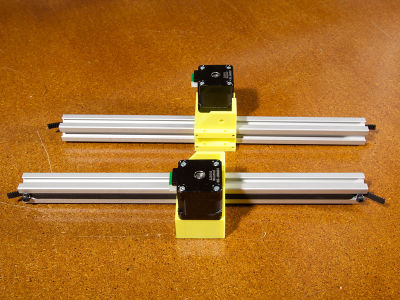
repeat the previous operations with the second y-axis

x4 M4x8
x4 T-nut


Step 11/18 - X-slider
X-slider
 x1 x-slider
x1 300mm profile
x1 x-slider
x1 300mm profile
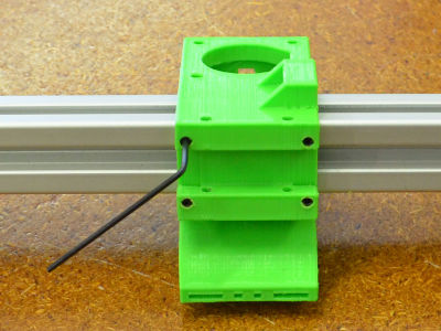
![]() x4 grub screw
x4 grub screw
make sure that the x-slider slides easily with no play on the aluminium profile (if not: file a bit the inside part of the printed piece until it slides well)
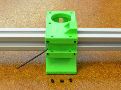
if necessary: reduce the play between the printed part and the aluminium profile with the 4 grubscrews


x1 nema 14
x1 pulley
![]() x2 grub screw
x2 grub screw
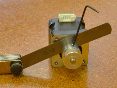
check the alignement of the pulley teeth with the x-slider


x2 M3x30 countersunk


x1 360mm belt
x2 M3x30 countersunk
x2 603zz bearing


x2 300mm profile


x2 x-belt end
x2 M4x8
x2 T-nut


Y-endstop


X-endstop


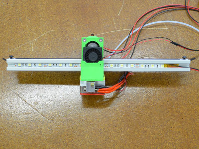
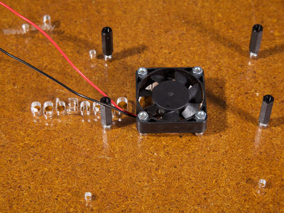
Blower
 x1 blower
x2 ferrule
x2 heatshrink tubing
x2 cable terminal (1mm)
x1 blower
x2 ferrule
x2 heatshrink tubing
x2 cable terminal (1mm)


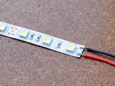
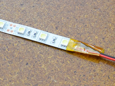
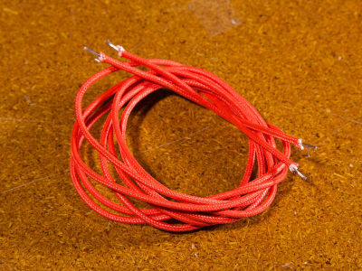
LEDs strip
cut 60cm of red/black wires + 2-pin connector


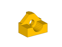
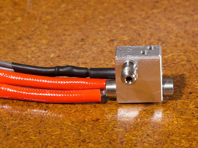
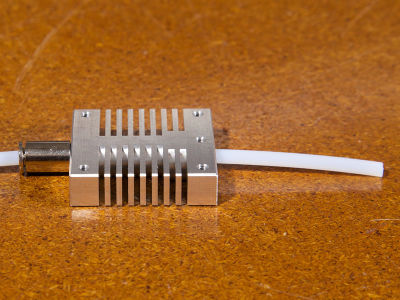
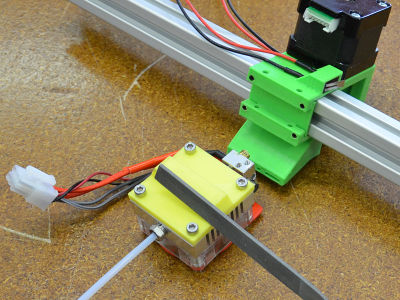
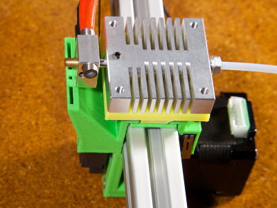
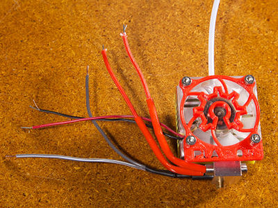
Step 12/18 - Hotend
Hotend
 x1 heater block
 x1 nozzle
 x1 barrel

screw the nozzle in the heater block (be careful with the nozzle orientation) until the flat part of the nozzle is aligned with the bottom part of the heater block
screw the barrel in the heater bloc until it touches the nozzle


 x1 thermistor
![]() x1 grub screw
x1 grub screw

position the thermistor in the heater block (be careful with the wires orientation)...

... and lock it with a grub screw


 x1 cartridge heater
![]() x1 grub screw
x1 grub screw
position the cartridge heater in the heater block (be careful with the wires orientation)...
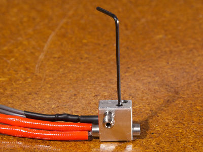
... and lock it with a grub screw


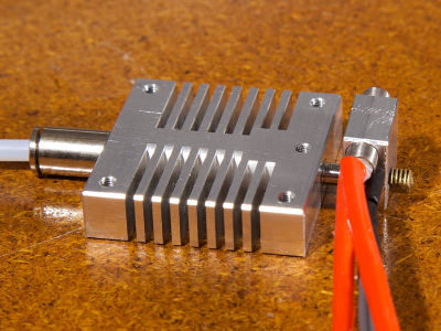
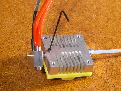
 x1 heatsink
 x1 pneumatic fitting
 x1 PTFE tube
![]() x1 grub screw
x1 grub screw
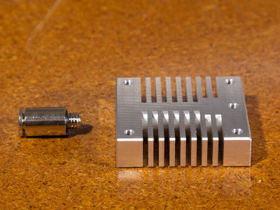
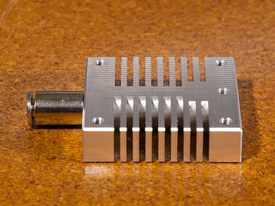
screw the pneumatic fitting in the heatsink
pass the PTFE tube through the pneumatic fitting and the heatsink

push the PTFE tube completely in the barrel

push the barrel through the heatsink WHILE pushing the ring of the pneumatic fitting (make sure that the PTFE tube doesn't move up in the barrel)
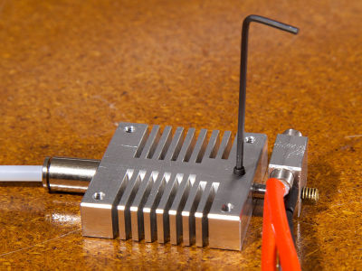
lock the barrel in the heatsink with a grub screw once the barrel shoulder is aligned with the bottom part of the heatsink (~5mm)


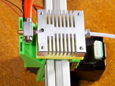
 x1 hotend holder
 x4 M3x8

turn the heatsink on the other side: position the hotend holder over the heatsink and screw it with M4x8

file both sides of the support...

... unitl it fits perfectly with the x-slider and it is still easy to slide the whole head from one side of the profile to the other
if the bottom heater block is not well aligned with the upper part of the spout holes...
... unlock the grub screw and adjust the height (make sure that the PTFE tube doesn't move up in the barrel)...
... and lock it in the correct position


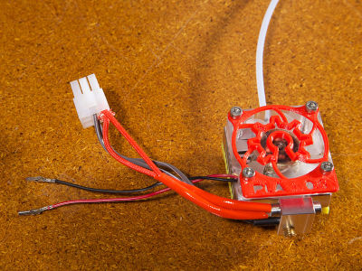
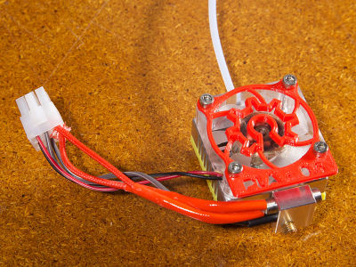
 x1 fan grill
x1 fan
x4 M3x16
x4 M3 washer
x1 fan grill
x1 fan
x4 M3x16
x4 M3 washer


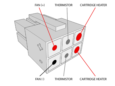
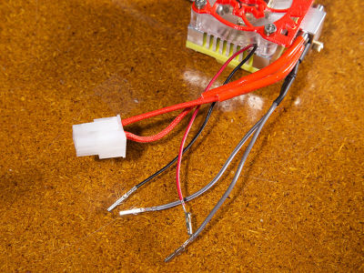
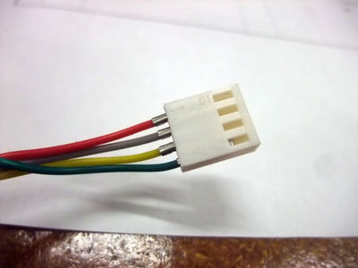
 x1 6-pin male casing
x6 female ferrule
x1 6-pin male casing
x6 female ferrule
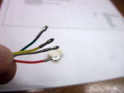
strip the extremities

crimp one female ferrule on each extremity...
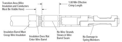
... just like on the drawing
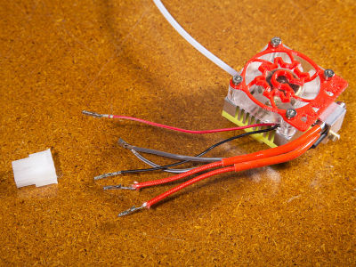
... just like on the drawing


x2 M3x25


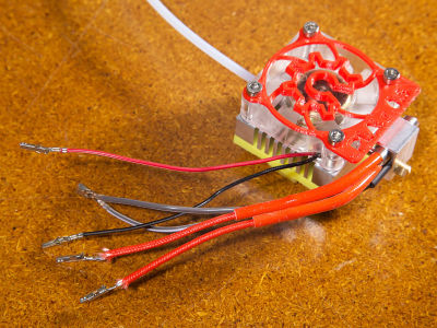
Cable harness
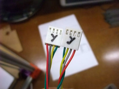
 x1 6-pin female casing
 x6 male ferrule

... just like on the drawing


x2 cable terminal (1.5mm)
plug both connector and make sure that the cables alignment is correct and that the ferrules don't go out from their casing


X-axis
x4 M4x8
x4 T-nut


Step 13/18 - Back panel
Plugs & Switch
 x1 4,8mm ferrule (+ insulation)
x1 6,35mm ferrule (+ insulation)
x1 4,8mm ferrule (+ insulation)
x1 6,35mm ferrule (+ insulation)


x1 4,8mm ferrule (+ insulation)
x1 6,35mm ferrule (+ insulation)


x1 6,35mm ferrule (+ insulation)


x1 4,8mm ferrule (+ insulation)


x1 4,8mm ferrule (+ insulation)


 x1 panel-back
 x1 plug
 x1 switch
x2 M3x8
x2 M3 nut
x1 switch
x2 M3x8
x2 M3 nut


 x1 USB port
x2 M3x8
x1 USB port
x2 M3x8


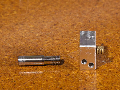
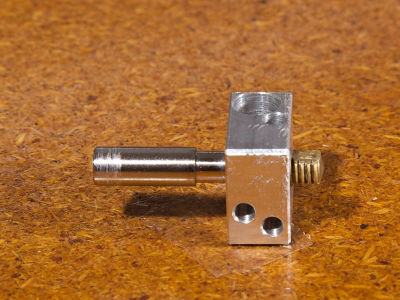
Extruder
x1 nema 17
 x1 insert

 x1 extruder
x1 M3x16
x1 603zz bearing
x1 extruder
x1 M3x16
x1 603zz bearing


x1 pneumatic fitting


x3 M3x25


 x2 M3x35
![]() x2 spring
x2 M3 washer
x2 M3 nut
x2 spring
x2 M3 washer
x2 M3 nut


 x2 door-lock-inner
 x2 door-lock-outer
x2 M3x12
x2 M3 nut
x2 door-lock-outer
x2 M3x12
x2 M3 nut


x6 M4x8
x6 T-nut

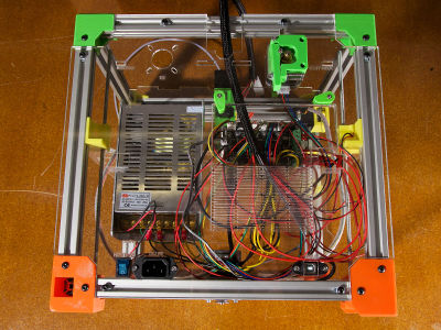
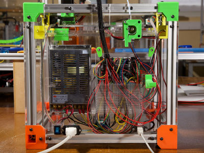
Electronic panel
 x1 electronic-cover-1
x1 fan
x4 M3x16
x4 M3 nut
x1 electronic-cover-1
x1 fan
x4 M3x16
x4 M3 nut

x4 M3x8
 x4 strut
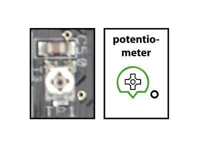

turn the potentiometers COUNTERCLOCKWISE and SLOWLY to position them like on the drawing


x4 M3x8

 x1 power supply
x4 M3x8
x4 M3 nut
x1 power supply
x4 M3x8
x4 M3 nut


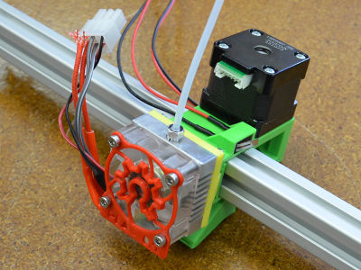
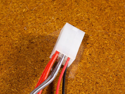
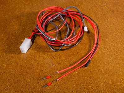
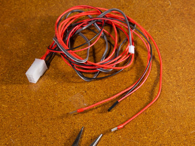
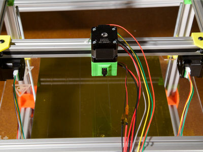
Step 14/18 - Wiring
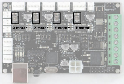
X-motor
add long wires + connector to the x-motor

Y-motors
bring the wires from Y-motor 2 out of the connector related with the electronic board...
... and invert them
bring the wires back in the connector


Z-motor
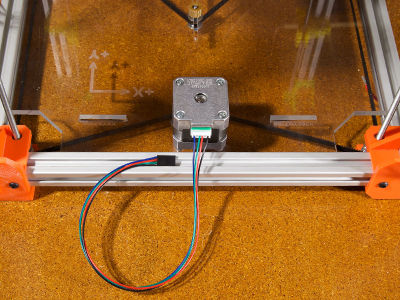
add short wires + connector to the z-motor

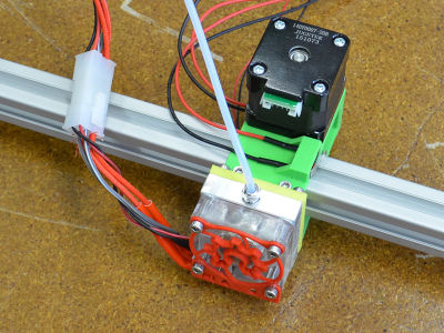
E-motor
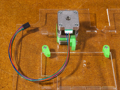
add short wires + connector to the extruder motor

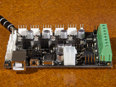
Electronic board

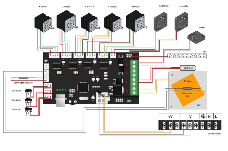
connect the wires according to the drawing (be careful with the wires colour)


pass the cables over the aluminium profile...
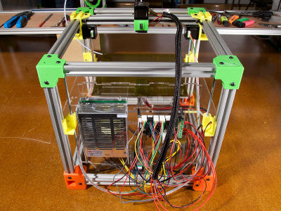
... and group them with the breaded sheath


Step 15/18 - Finishing touches
Cables-path
x1 M4x8
x1 T-nut


Electronic cover
 x1 electronic-cover-2


Endstop
 x1 endstop-stop
x1 M4x8
x1 T-nut
x1 endstop-stop
x1 M4x8
x1 T-nut

Panel-sides
 x2 panel-side
x8 M4x8
x8 T-nut
x2 panel-side
x8 M4x8
x8 T-nut


PTFE tube

Spool holder
 x1 spool-holder


Noodles cup
 x1 cup

Door
 x1 door
x5 M4x8
x5 T-nut
x1 door
x5 M4x8
x5 T-nut
Step 16/18 - Driver
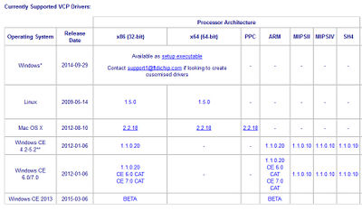
download the adapted driver on: http://www.ftdichip.com/Drivers/VCP.htm
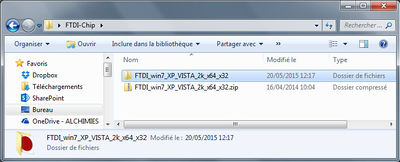
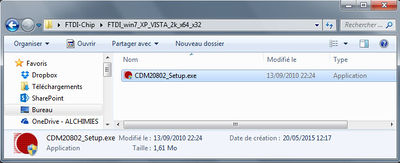
instal the driver

connect the 3D-printer to your computer
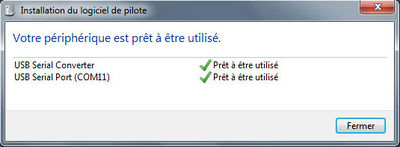
note the USB port COM number


Step 17/18 - Firmware
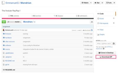
download the Mondrian file on: https://github.com/EmmanuelG/Mondrian
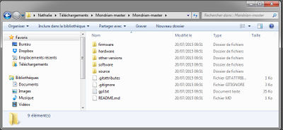
extract the files
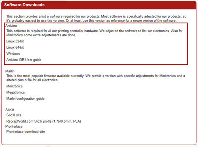
download Arduino 1.6.3 on: http://reprapworld.com/?software
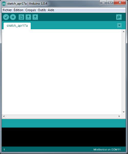
open Arduino 1.6.3
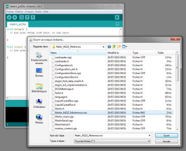
open the .ino file: Mondrian > Firmware > Marlin_M222_Minitronics > Marlin_M222_Minitronics.ino
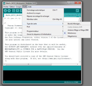
select the electronic board type > Ministronics
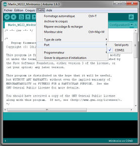
select the port COM number
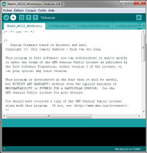
transfer the firmware on the electronic board


Step 18/18 - Software
User interface
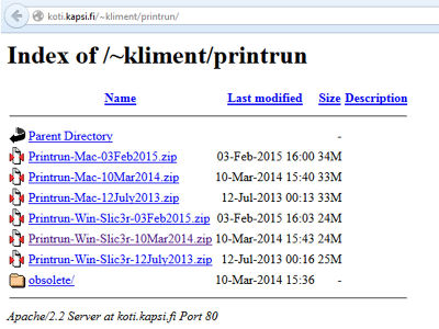
download printrun 03Feb2015 on: http://koti.kapsi.fi/~kliment/printrun/
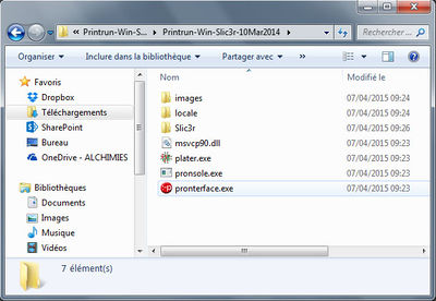
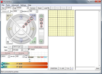
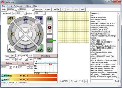
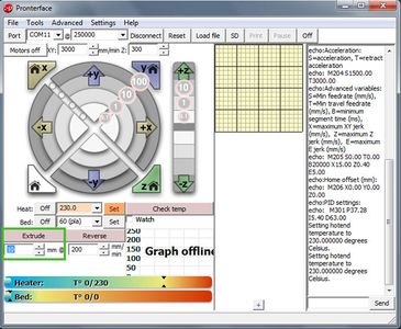
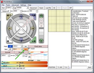
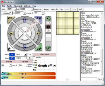
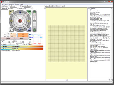
extract the files and open Pronterface
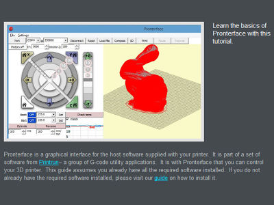
here is a short tutorial on Pronterface: http://www.plasticscribbler.com/tutorial/getting-started/item/21-getting-started-with-pronterface#.VZZMAUaVM9p
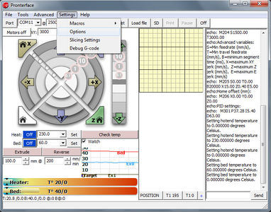
open the otpions panel
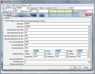
enter the bed size: 200x200x200
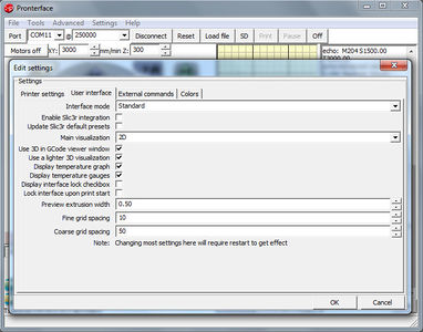
tick the box "display temperature gauges"


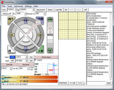
Testing
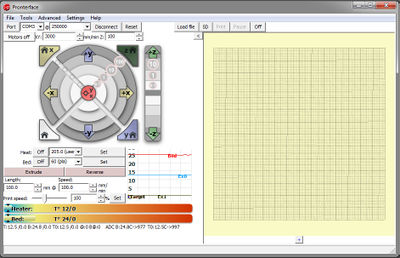
connect the Mondrian

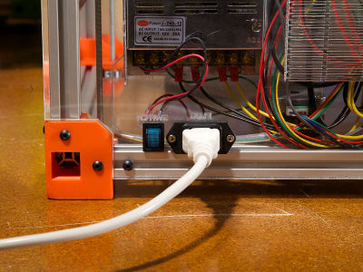
switch on


X testing
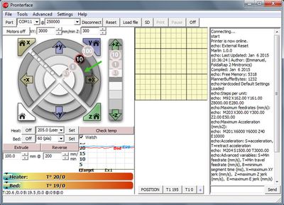
test the x-motor movement: (+)10X moves the hotend of 10mm to the left (the hotend moves away from the x-endstop)
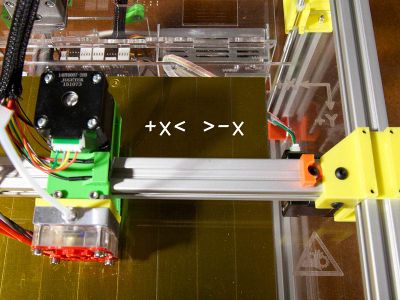
(-)10X moves the hotend of 10mm to the right (the hotend moves closer to the x-endstop)


If the motor rotation is reversed go the the "readjustments" paragraph...
Y testing
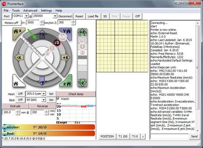
test the y-motor movement: (+)10Y moves the hotend of 10mm to the front (the bed moves away from the y-endstop)
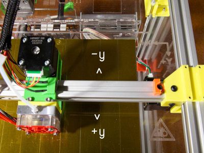
(-)10Y moves the hotend of 10mm to the back (the bed moves closer to the y-endstop)


If the motor rotation is reversed go the the "readjustments" paragraph...
Z testing
test the z-motor movement: (+)1Z moves the bed of 1mm to the bottom (the bed moves away from the z-endstop)
(-)1Z moves the bed of 1mm to the top (the bed moves closer to the z-endstop)


If the motor rotation is reversed go the the "readjustments" paragraph...
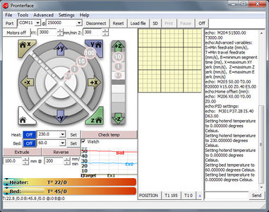
Hotend testing and adjustment
set the hotend temperature to 230°C

remove the hotend from the x-axis (be careful: it's hot! use gloves): as the metal parts distort because of the heat it's necessary to screw tighter the nozzle in the heater block to make the junction with the barrel airtight
use 2 pair pliers to do that: 1 pair to hold the heater block and 1 pair to screw the nozzle
replace the hotend on the x-axis


Extruder testing
while the hotend is hot push the extrude botton with 10mm (if the hotend temperature is <150°C the printer will protect itself and won't extrude)
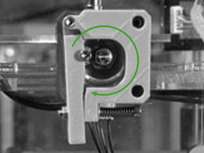
the e-motor turns clockwise
stop heating up the hotend


If the motor rotation is reversed go the the "readjustments" paragraph...
Bed testing
set the bed temperature to 60°C
stop heating up the bed


Readjustments
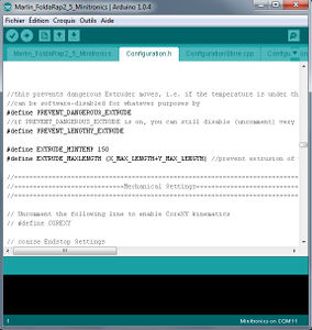
if the motors rotation is reversed then disconnect the 3D-printer from Pronterface and re-open the firmware in Arduino 1.6.3 >> Configuration.h >> "Mechanical Settings" paragraph
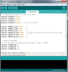
define INVERT_?_DIR false // write "true" instead of "false" (or the contrary) for the axis which need to be reversed and transfer the new version of the firmware on your electronic board
test again the motors rotation


Endstops testing


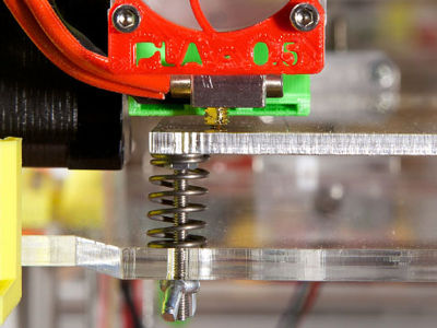
Step 19/20 - Bed calibration
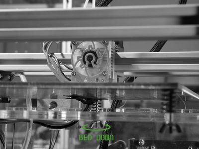
thanks to the Pronterface console move the bed down (+)3Z...

... and bring the nozzle over the first M3x30 countersunk (+)X and (+)Y
bring the nozzle to "0" (HOME Z)

IF the nozzle puts pressure on the bed...
... turn the bed adjuster counterclockwise...

... until the nozzle touches the bed without putting pressure on it

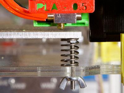
IF the nozzle doesn't touch the bed...

... turn the bed adjuster clockwise...
... until the nozzle touches the bed without putting pressure on it
thanks to the Pronterface console move the bed down (+)3Z...

... and bring the nozzle over the second M3x30 countersunk (+)X and (+)Y
bring the nozzle to "0" (HOME Z)
turn the bed adjuster until the nozzle touches the bed without putting pressure on it
thanks to the Pronterface console move the bed down (+)3Z...
... and bring the nozzle over the third M3x30 countersunk (+)X and (+)Y
bring the nozzle to "0" (HOME Z)

turn the bed adjuster until the nozzle touches the bed without putting pressure on it
move the bed down (+)3Z...


1ère impression
Modélisation
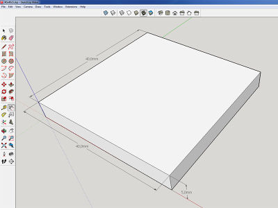
dessinez un parallélépipède de 40x40x5mm sur le logiciel de CAO de votre choix : Blender, 3D Slash, SketchUp, etc.
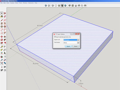
exportez le parallélépipède au format .stl (ainsi qu'au format du logiciel de CAO)


Netfabb Basic
Vérifiez la qualité de votre fichier .stl sur Netfabb Basic : vous pouvez "réparer" ou retravailler votre fichier .stl
téléchargez et installez Netfabb Basic à partir du lien suivant : http://www.netfabb.com/downloadcenter.php?basic=1
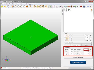
ouvrez votre fichier .stl dans Netfabb Basic : si le fichier est correct, toutes les faces de l'objet apparaissent en vert et le logiciel transmet la valeur du volume dans le panneau de droite (vous pouvez également vérifier les dimensions de votre modèle)
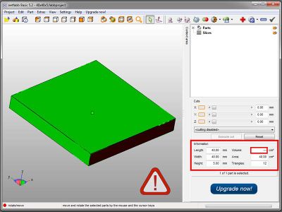
si le fichier .stl est mal conçu, un panneau "!" apparaît et le logiciel n'est pas capable de communiquer la valeur du volume du modèle
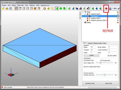
pour réparer le fichier .stl : cliquez sur le bouton symbolisant une croix rouge (REPAIR)
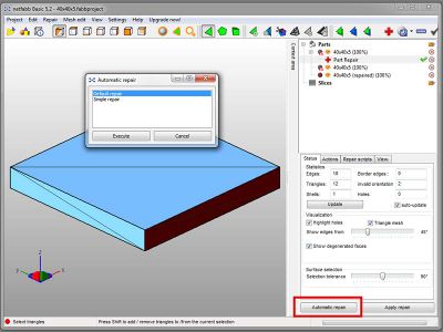
sélectionnez l'option "automatic repair"
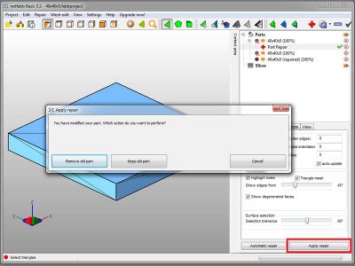
appliquez les réparations ("apply") et écrasez l'ancienne version du fichier ("remove old part")
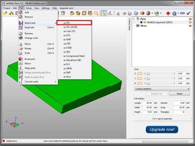
pensez à sauvegarder la nouvelle version de votre fichier : Part > Export part > as STL
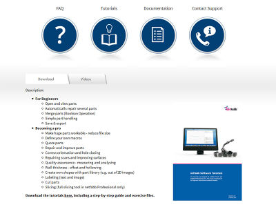
si vous souhaitez en savoir plus sur les fonctionnalités de Netfabb Basic, vous pouvez télécharger les tutoriels sur le lien suivant : http://www.netfabb.com/tutorials.php


Si les réparations automatiques ne permettent pas de réparer la totalité du fichier .stl : utilisez le bouton "repair" pour identifier l'origine des problèmes et ouvrez à nouveau votre fichier sous l'extension de votre logiciel de CAO afin de corriger les problèmes manuellement (pensez à ré-exporter la nouvelle version de votre modèle au format .stl)
Slic3r
Définissez les paramètres d'impression de votre objet dans le logiciel Slic3r
téléchargez Slic3r sur le lien suivant : http://slic3r.org/download
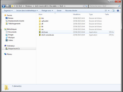
extrayez les fichiers et exécutez slic3r.exe
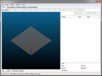
la fenêtre Slic3r s'ouvre sans aucune installation
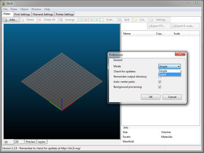
changez le mode-utilisateur : File > Preferences > Mode > Expert (fermez et redémarrez Slic3r afin de prendre en compte les changements)

chargez le fichier de configuration adapté à la FoldaRap (à partir du fichier FoldaRap-master de la plate-forme GitHub): File > Load Config... > FoldaRap-master > software > config.ini (choisissez "05nozzle" si le diamètre de votre buse est de 0.5mm)
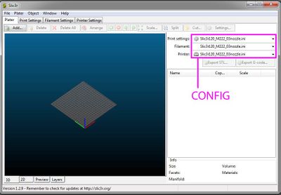
vérifiez que la configuration est bien chargée
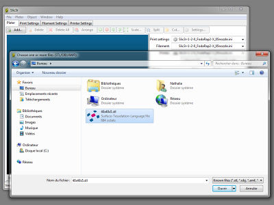
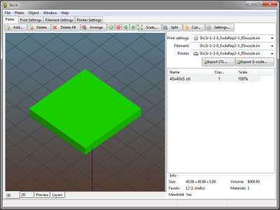
ouvrez le fichier .stl dans Slic3r : Add... > Fichier.stl
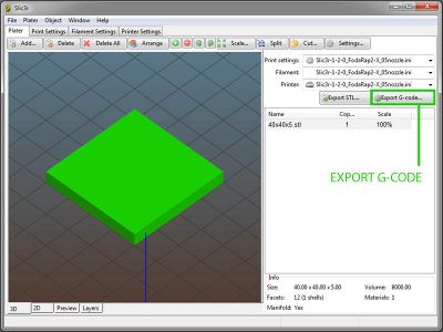
exportez le G-code contenant tous les paramètres concernant : l'objet (Print) / le plastique (Filament) / l'imprimante (Printer)
consultez le manuel Slic3r si vous souhaitez en savoir plus sur les différents paramètres : http://manual.slic3r.org/


Pronterface
Pilotez votre imprimante-3D avec Pronterface
la fenêtre Pronterface est certainement encore ouverte et votre imprimante encore connectée... si non : démarrez à nouveau Pronterface et connectez votre machine sur le bon port COM @250000
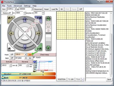
chauffez le plateau à 60°C...
... et chauffez la tête d'impression à 205°C

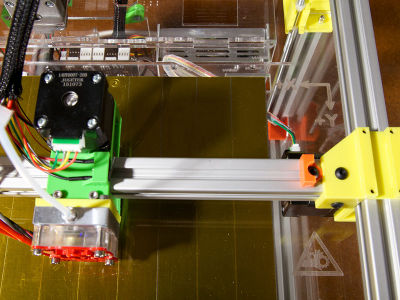
positionnez la bobine sur le support pour bobine
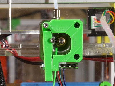
passez le filament à travers l'extrudeur...

... entre la poulie et le roulement...
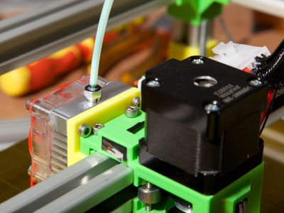
... puis poussez manuellement...

... jusqu'à ce que du plastique fondu passe à travers la buse (utilisez la pince pour retirer le plastique)
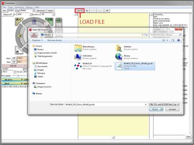
chargez le fichier G-code dans Pronterface...
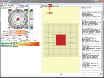
... et imprimez : la tête d'impression et le plateau vont se placer à l'origine (X/Y/Z) avant le début de l'impression
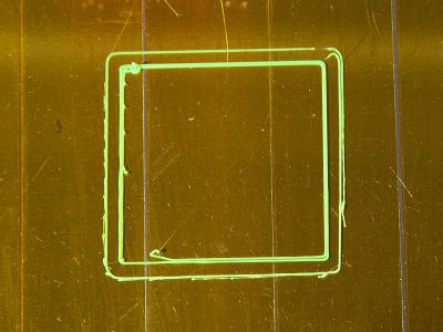
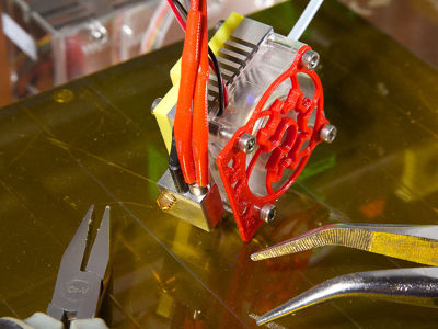
vérifiez la qualité d'impression : SI la buse est trop éloignée du plateau, le filament n'adhèrera pas sur le Kapton (le filament dessinera des petites vagues)
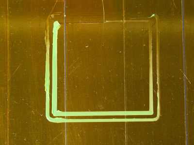
SI la buse est trop proche du plateau, le filament sera trop épais, voire ne pourra pas être extrudé
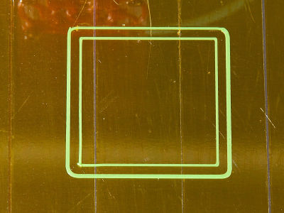
si vous observez l'une ou l'autre de ces situations, ajustez le niveau du plateau à l'aide des 3 molettes jusqu'à ce que l'aspect du filament se rapproche de la photo
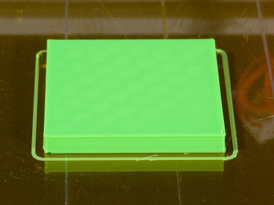
lorsque l'impression du parallélépipède est terminée, patientez jusqu'à ce que la température du plateau ait atteint 45°C avant de retirer l'objet (autrement vous risquez de la déformer)

vérifiez les dimensions de l'objet à l'aide d'un pied-à-coulisse (+/- 0.05mm)...
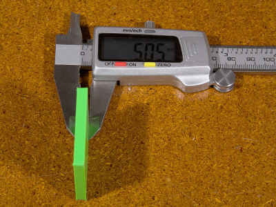

... et la précision des angles à l'aide d'une règle et d'une équerre (si la précision n'est pas satisfaisante, vous devrez ajuster la géométrie de votre machine : parallélisme et perpendicularité des profilés aluminium)


Votre Mondrian est maintenant terminée. A vous les innombrables projets !