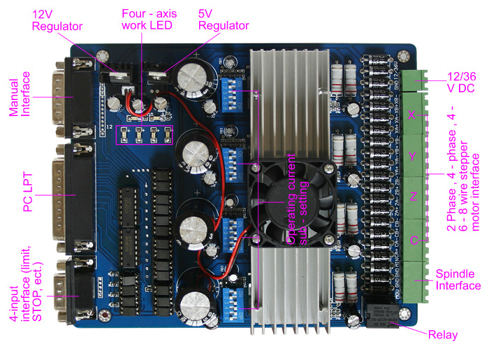
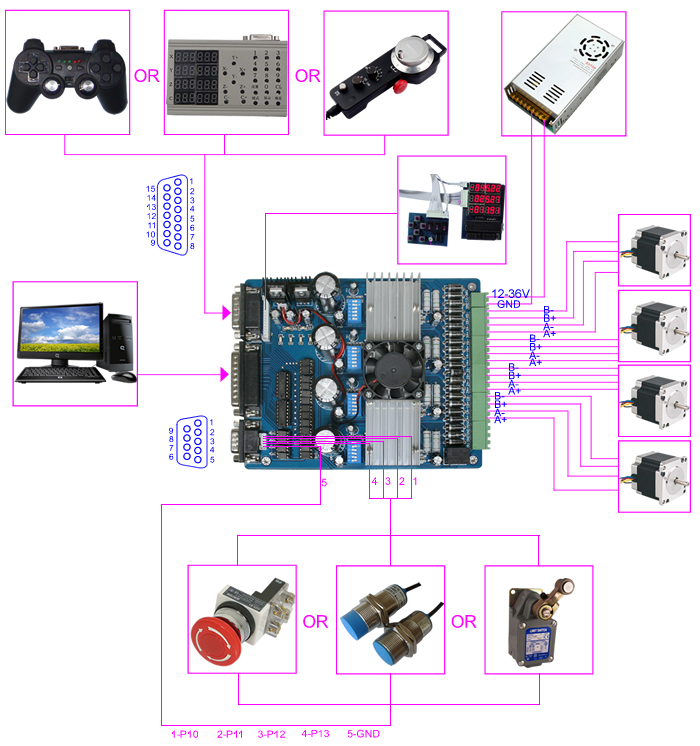
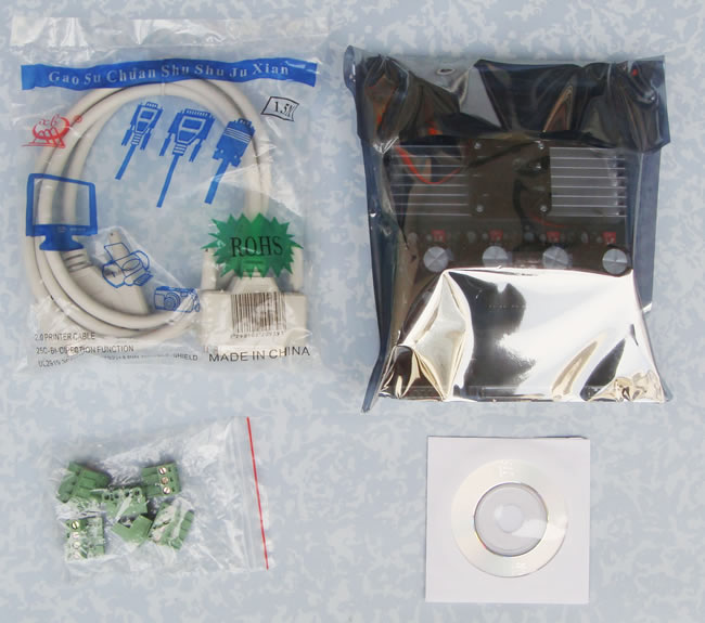
4 Axis TB6560 CNC Stepper Motor Driver Board Controller
Note: this board is neither reprappable nor open source, so it's a bit questionable whether it belongs into this Wiki.
Bogdan stuffed it into the wiki since he's using one or two,
and he suggests folk may want to check them out.
I think he bought his off of ebay.
No one's going to stuff it into the "Official" Electronics any time  soon.
--Sebastien Bailard 06:07, 11 April 2011 (UTC)

?! Maybe this is for "discussion page" and not for here. Why is it important if
the board is reprapable or not?! Are sanguino, arduino, pololu driver or any other
of many drivers we use reprappable ?!
Here we go anyways:
NOTE: This stepper driver board is HIGHLY experimental within the reprap community ( less than 3 known users, none 100% satisfied with their configuration yet)
NOTE: When I contacted ebay seller about the faulty driver board (they delayed sending me replacement) he told he they had received 3 faulty boards at once and were asking which one is mine
NOTE: During tests I managed to kill 3 different TB6560 drivers (one by just hooking scope to the output)
NOTE: This board is closed source, which means we'll have oodles of trouble printing it. A reverse engineered schematic of the 3 axis variant of these boards is available at http://www.cnc.info.pl//files/schemat_sterownika_3_osie_165.pdf
Users of this family of Chinese boards should be aware that many, if not all, apply power to the TB6560 in completely the wrong order. The chip spec sheet calls for the 5V logic supply to be applied and settled before the motor drive voltage is applied. There is a belief in some of the user community that absence of the logic voltage allows the upper and lower MOSFETs within the internal H-bridge to both be in a conductive mode simultaneously. There have also been reports pointing out poor slew rate with some of the opto-isolators fitted to these boards leading to missed steps and the incomplete isolation provided in that there is a common earth plane between the input and output.
here is the original manufacturer's site, in chinese
google translation of the above site
NOTE: If you want something more reliable, SOC Robotics also has a DB25 style breakout board (MK4, MK4c, MK5) and TB6560 driver boards that may work in place of this China board with less problems http://www.socrobotics.com
NOTE: For a video and some information on using the "Red" and "Blue" boards visit http://whatisacnc.com/driver-board/tb6560/
TIP: the model commonly used appears to be a HY-TB4DV-M.
The 'TB' means it uses the 6560 chip ( TA means the TA8435 chip, which is also used on a similar board).
The '4' means the number of channels.
The -M and -N boards have different physical layouts, and may be different revisions of the same basic design, not sure?
| Input Power | 12 - 36V DC Note that many forums state that this board dies in smoke if powered over 24V |
| Stepper motor drive current | 1.5A - 3A/phase |
| Drive type | Double-pole constant flow PWM actuation output |
| Compatible Stepper motors | 2 or 4 phase, 4,6 or 8 lead stepper motors, 3A max. |
| Dimensions | 18 * 11 * 4 cm (L*W*H) |
The pinount in the provided document was wrong (completely) so I traced the pcb for real values and here they are:
| Pin | LPT | Driver |
| 1 | (strobe) | X-CW/CCW |
| 2 | (D0) | RELAY (heater) |
| 3 | (D1) | Z-CLK (step) |
| 4 | (D2) | X-ENABLE |
| 5 | (D3) | Z-ENABLE |
| 6 | (D4) | Z-CW/CCW (direction) |
| 7 | (D5) | Y-CW/CCW (direction) |
| 8 | (D6) | E-CW/CCW (direction) |
| 9 | (D7) | E-CLK (step) |
| 10 | (ACK) | INPUT (limit switch) |
| 11 | (BUSY) | INPUT (limit switch) |
| 12 | (PE) | INUPT (limit switch) |
| 13 | (SEL) | INPUT (limit/stop switch) |
| 14 | (AFEED) | Y-CLK (step) |
| 15 | (ERROR) | N/C |
| 16 | (INIT) | X-CLK (step) |
| 17 | (SELIN) | Y-ENABLE |
| 18 | GND | GND |
| 19 | GND | GND |
| 20 | GND | GND |
| 21 | GND | GND |
| 22 | GND | GND |
| 23 | GND | GND |
| 24 | GND | GND |
| 25 | GND | GND |
You may find that the fourth stepper driver enable pin is not available on the DB25 connector. If so, it is on the DB15 at pin 1.
ALTERNATE: In some revisions at least, the enable pin for the fourth driver/channel is *SHARED* with the enable pin for the third channel ( assuming you wire them in the order XYZE, it means that your Z and E drivers share their enable line ).
-Also i received aboard this week that had pin 17 inverted for y axis to be enabled. -james villeneuve (edited 12/6/2010) - if you use a stepper board, be sure to test the configuration out quickly with a parallel port program. my preference is to test with mach3, it is open source and easy to configure in windows. it is however not open source. i would use emc2 to test it if you are in linux. setup example for emc2 is here: http://makeyourbot.blogspot.com/2010/02/making-emc-do-printer-dance.html mach3 free demo version here (full test but 500 gcode limit) here: http://www.machsupport.com/downloads.php I am not associated with mach3, and only use it here for reference. feel free to edit or remove mach3 comments if it is not appropriate. james villeneuve profounddevices 12/6/2010
another issue, is people need to common both the electronics and the controller to a common gnd. do this by having pin 25gnd, connect to arduino gnd.
| Pin | CNC |
| 1 | E-ENABLE |
Note: The enable pin's are pulled high so if you do not drive them
all drivers are enabled by default.
[ -> not necessarily true. i have found that i need to ensure that they are driven high/low whatever state is enabled.
also in reprap firmware you need to make it non inverting enabled. reprap gen 3 is inverted for enabled. these electronics are non inverted for enabled. (james villeneuve) 1/19/2011]
| Current Setting | 1 | 2 | Decay Mode Settings | 3 | 4 | MicroStep Settings | 5 | 6 |
| 100% | ON | ON | FAST | ON | ON | 1 | ON | ON |
| 75% | ON | OFF | 25% | ON | OFF | 1/2 | ON | OFF |
| 50% | OFF | ON | 50% | OFF | ON | 1/8 | OFF | ON |
| 25% | OFF | OFF | SLOW | OFF | OFF | 1/16 | OFF | OFF |
The currently recommended settings for the DIP switches are:
X & Y axis: 25% Current, Slow Decay Mode, No Microstepping ( ie use Microstepping value of 1 ) ie: OFF,OFF,OFF,OFF,ON,ON.
Z: To-be-determined. Currently we believe the required power setting may need to be higher than X& Ym, but we arent sure. No Microstepping. perhaps: OFF,ON,OFF,OFF,ON,ON.?
Extruder: To-be-determined. No Microstepping.
NOTES: You need to avoid microstepping unless you have the absolute latest firmware, because with *lots* of microstepping interrupts on all axes, you will get packet loss on the USB-Serial Host communications. For now, the fix is to avoid microstepping. It makes it easier to debug lost steps, etc anyway.
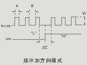
Signal waveform and timing:
The attached image seems to imply that there is a requirement to have the "step" pin pulled low while the direction pin undergoes a change. It also seems to imply that there should be a quiescient period before and after the change labeled "2C". A is the pulse width, B is the inter-pulse width, and 'C' is the required quiensent time before and after a direction change. The minimum values for A, B, and C are not known at this time, but may possibly be calculated experimentally. please update the wiki page if you have more information on this.
I have been fiddeling around with the above driverboard and couldn't get it to work with Mach3. After looking around on the web, I found out it should work with LinuxCNC.
The settings used for Mach3 are the best to use in LinuxCNC, but leave the "enable" pins out.
| Pin 2 = Spindle on | Pin 1 = X direction | Pin 16 = X step | Pin 7 = Y direction | Pin 14 = Y step | Pin 6 = Z direction | Pin 3 = Z step | Pin 8 = A direction | Pin 9 = A step |
(Been turning "reverse" on and of to see what this would do, in my case the leds start to burn but the motor wouldn't run).
I have put all the microswitches on the driverboard to ON.
But I am still fighting with the speed setup of the steppermotors.
(If I have any news, I will post it here.)
Where to get it?
You can get it on SainSmart.com
Someone running a 3D printer using the TB6560 using Mach3 GUI, not a printer yet though http://www.whatisacnc.com/index.php?cID=242


