Buckrap Hot End Bow
Release status: working
| Description | Buckrap Hot End
|
| License | |
| Author | |
| Contributors | |
| Based-on | |
| Categories | |
| CAD Models | |
| External Link |
Contents
Buckrap's Hot End
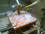
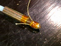
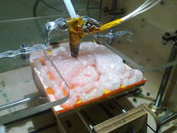
Here is a simple design for a Hot End. Using the minimum of custom parts and no machine tools it is possible to make a lightweight hot end that is compact and a perfect match for a Bowden extruder. Due to the minimal mass it is easy to mount onto any platform, here some perforated assembly strap is used. This strapping is often used by car audio technicians and others to position radios and speakers; a copper version of this strap is used by plumbers in some countries to make mechanical earth connections across plastic traps in drains. However any rigid mounting means is suitable.
Design methodology
The simplifications that have been used here are:
- The classic hand wound heating element
- A lack of machined mounting of the nozzle to metal or rigid insulator by clamping or screwing
- No fibre or ceramic insulation is used
- No epoxy or cement adhesive is used
- A single assembly consumable (Kapton Tape) is used
- The PTFE Bowden tube serves as the hot end liner
- The Bowden tube is directly inserted into the hot end without additional fittings.
- The Kapton tape is used to replace the low temperature insulation avoiding silicone insulated wires
- Use of a simple M6 nut for tapping of the PTFE tube
This does give rise to some limitations:
- Complete disassembly, with likely loss of thermistor, heater and all the tape, is needed for repairs or nozzle changes
- The accuracy of the mounting is approximate and the Z height may change if the nozzle is bumped
- Clearing a jam may be hard as the Bowden cable is firmly attached
Parts
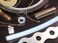
Total costs typically under EUR15 / US$20:
- PTFE Tube 6mm (external diameter) 30-50 cm
- Brass nozzle 0.5mm extruder and M6 (purchased from Camiel)
- M6 Nut (used for cutting threads onto the PTFE tube)
- M6 Brass coupling tube (photo)
- Insulated Nichrome wire
- Thermistor
- Perforated assembly strap 6mm holes (in the lower-right corner of the parts picture)
- Kapton Tape 5mm (and optionally 10mm)
- Crimp on terminals 1mm
- Wire
Tools
- Pliers
- Wire cutter
- Crimping tool for terminals
- Scissors
- Spanner 10mm for M6 nut
- Multimeter
Assembly
Mechanical fitting
- First push the M6 nut on PTFE tube (you can chamfer the end of the tube a bit with a knife or pencil sharpener) and use the spanner turn it about 2 cm along tube. Then turn back the nut and remove it.
- Cut the end of the PTFE tube square with a sharp blade (you may try cutting it just before you remove the nut if it seems easier)
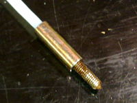
- Turn the tube into the brass coupling
- Turn the brass nozzle into the coupling until it meets the PTFE tube
Wind the heater
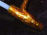
- Tape the coupling and the brass nozzle with the Kapton tape
- Wind the Nichrome wire (Length about 28cm and check for about 6 Ohm resistance)
- Tape over the Nichrome wires to hold in place
- If you are careful you may be able to wind un-insulated Nichrome wire by laying it into the threads of the nozzle but holding it in place and preventing turns crossing while taping will be hard work
Prepare the thermistor
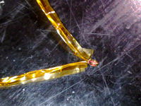
- Insulate the thermistor leads with Kapton tape
Connect wires
Take attention here
- Strip low temperature insulation from 2 wires for 7cm
- Strip low temperature insulation from 2 wires for 4cm (thermistor leads are already quite long)
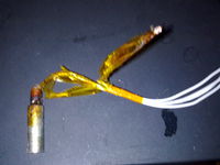
- Crimp the long ends to the Nichrome heater wire ends
- Crimp the short ends the thermistor leads
- Insulate all wires individually with more Kapton tape
Tape up hot end
- Tape the wires together and then tape them to the coupling
- Position the thermistor near the junction of the nozzle and the coupling and tape it in place tightly
- Arrange the wires to extend from the assembly below the final clamping zone at the top and tape in place
- Insulate the top of the coupling (thermal insulation to prevent mounting from cooling the nozzle)
- Insulate the tip of the nozzle (thermal insulation to prevent ambient cooling of the heater zone)
Mount to platform
- Hold the wires out of the way so they are not clamped to prevent short circuits
- Use perforated assembly strap for mounting there are no large forces to contend with but it must not vibrate
- Because the extruder cold end is remote there is very little mass that needs to be supported
- Close inspection of the picture shows the detail of how it was mounted on a MakerBot platform, the taped up assembly is clamped between two pieces of the perforated strap and the strap tails are then fastened onto the platform
