DIY Direct hot end
Release status: Experimental

| Description | Mostly DIY direct hot end - gas nozzle
|
| License | |
| Author | |
| Contributors | |
| Based-on | |
| Categories | |
| CAD Models | |
| External Link |
Contents
Disclaimer and Introduction
At this point this is highly experimental, so use at your own risk. Also please edit, post on forum or pm opinions, findings, for the benefit of community - tyvm. Its not sure anything here will be an improvement over current design(s), or if it is any easier to DIY, this is the intention at least, but time should tell.
The older design has a small thread inside a PTFE, where it fits a brass barrel that has a hole alongside and inside it. Originally was using nichrome wire as heating element. I think now most ppls use heater blocks with heater resistors by attaching a heater block on the threaded barrel. There are 2 weak points in the use of this:
- the thread is very small number, thus has small teeths and doesnt grip the thermal barrier very good;
- attaching a heater block on the other end of the barrel makes it to act as a lever, as being subject to all the "giggling" of the reprap movements, inertia, moment forces etc (probably with original nichrome the solution was lighter and this had lower impact)
This variation tries screw the thermal barrier on the heater block, directly, without any middle pieces. Getting rid of the threaded barrel which can cause problems (hopefully without getting others instead). There are several other designs that more or less, do that, in one way or another, with PEEK or metal body and PTFE sleeving, etc. Among the diversity of hot ends out there, this page is not really all that original. Maybe the gas nozzle can be somewhat different (havent seen posts with that yet), although i am sure somebody somewhere is already using a gas nozzle just like that, but i just havent found myself any page mentioning that, although i have seen mig welding tips and similar.
Thermal barrier
Here it is assumed to be PTFE. PEEK is presumed to not work. There are several sorts of both PTFE and PEEK, see here http://forums.reprap.org/read.php?1,79524,80492#msg-80492. There is nothing absolutely generally valid about advanced plastics and usually what matters most is the additive material, which usually is not mentioned. The following are some ideas:
-a PTFE that is ivory-sh color, has a good chance of being the sort that has extra mechanical resistance and slightly worse friction (could be additivated with glass). Or if its the other similar type (rare), it should fail very soon.
-a PEEK that is black color, has a chance of being the sort that has improved less friction, also (could be additivated with graphite). Remember this is not confirmed to work, its mere theoretical. The most common PEEK sort (brown-grey) has been reported to NOT work. So commonly a PTFE tubing sleeve inside is used to reduce friction with the filament. Again, there is no PEEK sort confirmed to work in the exact role of the PTFE. The PTFE sort with graphite is mentioned as a *theoretical* possibility, so maybe someone who can get it might test it (unlike the common PEEK, this sort seems to have much less availability).
The thermal barrier(s) in the picture are 16mm diameter and 7 cm long. I had to make them longer than the version with the threaded barrel, to gain the barrel length. So the heater can come out of the carriage - i was afraid that if heater block is too much inside the carriage it may overheat it. Longer barrel increases the thermal dilatation proportionally, at least in theory if the temperature its uniform. Although its not uniform, the dilatation may get to be significantly more than in the case of a small height piece. This may also relate to the way it is mechanically supported.
The thread on it can be M10, M12, M14, M16 and it just needs to fit to the thread in the block. I initially used M10 but now i came to think that M12,14 and even 16 would be much better in comparison to M10, because they have more "meat" on, and around the thread area.
Heater block
Aluminium, brass or stainless steel? Probably aluminium because its lighter. However, its more fragile than the others so its threads might get damaged after repeated abuse about nozzle exchanges (good thing thread is on the inside). Brass is not too bad either. Stainless steel is hard to machine and has a lower thermal conductivity, availability is low so can be ruled out. Copper is a thought but availability is probably lower.
The thread of the PTFE joint in the picture is M10x1.5mm (standard) because that was the tooling and what i considered at the time of making, but M12 (standard x1.75mm) or even M14 would of had more "meat" between its "teeths", so probably better. Also non-standard threads, lesser pitch (like threads of 1.0mm/rotation) might be much better at leakage prevention giving a higher number of turns per same length. Heater block can be made virtually in any shape or form, probably best would be cylindrical but that may require a lathe. It can have also have one or more resistors, etc. After all considerents, probably heater block should not be too heavy, especially if its supported only by PTFE alone.
Leakage prevention is an important considerent: both threads are short enough, and are made from different materials (informative 150-250C dilatations*10^-6 in m/(m*K): PTFE 60; PEEK from 100 to 65; aluminium 25; brass 19?).
The heater block has a large thread for PTFE, and a small thread for the nozzle, which:
- should allow a tight fit of PTFE and nozzle to each other with no space in between,
- these threads have to be concentrical on the same axis,
- threads quality should be best possible.
1. The heater block height should be not more than the lengths of the PTFE thread and the nozzle thread added together, that is because there should be no space in between, and the lengths of each inside thread should perfectly match the piece it will fit, no more and no less.
2. The thread for the PTFE and the one for the nozzle needs to be done perfectly concentrical, which means the hole having 2 diameters will be done in same "catch" - without altering the position of the piece in vice or the position of the head of drill press. So before starting, make sure you have enough space to change the drill bits without altering anything.
3. Most of the threads done with a tool by hand will have a defect: the first few threads will be larger or even unusable. Probably because the tool is not concentric to the hole untill it starts to find the middle by itself - the hand cannot be precise ehough. So, if we make the thread for the nozzle, from the nozzle mounting side, first threads will get ruined and possibly the heater block will leak. Its much better to make the nozzle thread (smaller thread) starting from the inside of the block (from PTFE side of the block) and going outwards. So the exit of the thread, where nozzle will be fitted, will be best possible quality thread. First make the smaller nozzle thread starting with the tool from the pfte side, then start making the thread for pfte after. When mounting, PTFE plumbing tape can be used on the threads.
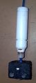
Nozzle

For a change this uses another nozzle type. This nozzle is found in any kitchen that has a classic cooking machine using natural gas or LPG. Its exactly the nozzle from which the gas comes out to be burned. Has certain diameters depending if the gas is methane or propane, and also depending on the size of the burner plate. Lift up the top of the cooking machine and you will see it. Sometimes it might be found on house heating furnaces that use gas or lpg. It is made from brass, threaded on the outside. From what i saw typically these nozzles holes are from 0.3mm up to 0.8mm (with alot of values in between) and with non-standard M6-7-8 thread pitches 1 step lower than the standard (at least that is what i found around) but no doubt the variation can be bigger than this:
M6x thread - gas nozzle pitch 0.6 (standard pitch is 0.80mm)
M7x thread - gas nozzle pitch 1.0 (standard pitch is 1.25mm)
M8x thread - gas nozzle pitch 1.0 (standard pitch is 1.25mm)
Tested in practice the M7 (switched 3 pcs) and M8 (tried 2 pcs). I suspect best is the one which has the inside hole close to the filament size + some margin so this way it seems to give a better, constant flow - (its the hole where melted filament should enter). Probably the inside hole will have much variation among different nozzle types, but to aim at a size just a little over filament size is probably best.
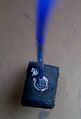
These nozzles have a blunt ending (like some do in the picture) and that should be changed on both of its ends. Without a lathe, i mounted the nozzle(s) in a chuck of a drill press and using a sharp tool i took few layers around the nozzle output to give it a small clearance to gave the nozzle a ... nose. The back side of the nozzle can use some shaping too, so the filament flows inside of it nicelly. I had successfully shaped my first nozzle after ruining 3 others. So buy some extra, if you are going to use "afgan lathe" you are probably going to need lots of extras. The picture shows the left side tip as a cylindrical shape but i found later that the conical shape works fine. Some opinions are that cone should have a flat tip (e.g. like extrusion diameter), although i tried making the tip as sharp as i could with thin walls and seems to work better (smaller traces when passing over infill and less plastic stuck to nose). Last operation on the cone surface can be fairly easy to be done with a file by hand, and even with sandpaper, so the resulting surface of the cone is smoother, and will be easier to clean up.
Tips for tweaking the nozzle with "afgan lathe":
- much of the material removal can be done by catching the nozzle in the chuck against its hexagonal side; this way thread wont suffer, hole will have better concentricity, and with proper tools (slim ones), probably all operations can be done this way;
- if its necessary to catch on the thread, to minimize thread damage, a little newspaper paper can be rolled on the nozzle thread prior to catching;
- to give it a better finishing, push a fine sandpaper with the finger against the sides of the rotating nozzle (cone area); dont sandpaper the very tip (flat area), that probably needs to be as straight as possible;
The nozzle just gets screwed inside the heater block. That means, it can get unscrewed to fit another, without dismantling everything. I have successfully printed with this, and also changed the nozzle directly. It is easier if the heater is at a temperature like 100-150C and if the heater block can be held in place with a wrench and the nozzle can be unscrewed with another wrench. So, make sure when making the block that a wrench will fit properly to it, from the front side of mounted position.
Mechanical Support (carriage and mounting)


Carriage
The current carriage doesnt really offer a clear simple way to fix this on it, so it needs either some improvisations, or another carriage, but most probably both.
My older mendel carriage trapped heat and i think it was pretty bad for a number of reasons, i looked on thingverse but none of the other solutions inspired me enough confidence, so instead of just printing one, i decided to make it different. Mostly inspired by Mr. Nophead's blog post Plumbstruder. What i did is to re-use a small alu plate (~5.5mm width), both as carriage and also as a radiator, getting rid of the classical carriage entirelly. Probably a radiator with fins, big enough, and with enough "meat" on the lower side, would of been much better than my simple plain plate - i just didnt had anything like that.
- vertical screws: most are only to one side (dunno english name for this screw setup, in my language its called "prezon"). To make it like that, tap lower diameter, e.g. to fit a M4*0.7 screw like that, tap M3.5*0.7 and it will be a slightly forced fit, and it wont get off easy. If you wish, put a drip of thread compound or nail polish (making a good use of a wife) and that screw piece will pretty much stuck there for good. On the top side, there are no screws coming out, except those 2 for extruder. Beware NOT to tap M3.5*0.6 instead of 0.7, because then the M4 screw will rip it off. To see if the M3.5 is 0.7mm/rev or not, put it on the M4 screw, look in light and inspect the contact area, you should see if all taper threads fill the screw threads in a good manner or not.
- horizontal screws: most of them are normal M4*0.7 tap, and after the thread its done, they have to be carefully cleaned inside of eventual debris, i consumed a toothpick and an average amount of my nerves.
- belt fitting: this was for a standard mendel, and for prusa the belts are in a different plane so would need a different mount type.
- axis constraints pieces: the constraints are made from 2 metal pieces bought from hardware store. Again dont know the name for those, are the pieces that look like a L (squared) and ~4 mm width, usually zinc-plated and are used to mount pieces of wood at 90 degrees corners, and i believe they are widely available in any hardware store.
- the 360 constraint: was made from a bigger piece, fairly sturdy, so the bearing angles i could adjust with some effort and still be confident its sturdy enough to stay like that in use. Its problem was that those 3 screws came pretty close to each other and to the rod nearby. On retrospect, to be easier to mount, i realized i had space between the 8mm rod and the carriage to let a longer part slide between these, and fit it with some screws to the other side towards the copper pipe. Probably would of been much better like that. Especially if it would of been big enough to solder the copper pipe directly on it, then the overall rigidity and also heat transfer from copper to aluminium would of been even better.
- the 180 constraint: i used only 3 bearings, the middle one use a small piece of same type, and uses 3 screws cut to size, and also M3.5*0.7 tap holes so there is no chance to come off during operation / vibration etc. The screw that is further away has a small washer near the carriage, so when the other 2 are screwed tight, they act like a lever to pull the bearing against the rod. When this occurs, the angle of the bearing may change slightly, but again the metal piece can be bent a little. Its not ideal, but can work.
- the copper pipe has 16mm interior, and its soldered to a piece of metal which in turn gets screwed to carriage. Its easy to solder with hard metal flux and a small gas (lpg) soldering tool. In absence of thse, maybe it can be done with prior sandpapering the contact areas, and on the flames of a cooking machine, but i havent tried it myself although i think it might just work.
- eventual fan mount: because of how belts mount, the only place i could see a fan being fitted was the opposite side, the side with the single bearing. Few horizontal holes through material (like the horizontal ones for bearings), can accomodate a 40mm fan i have. I havent actually mounted it yet, but i made the holes for it as "just in case" provisions. I think fan isnt needed if there is an acceptable thermal barrier (ptfe or else). But i think it would be indispensable in the lack of suck (e.g. all steel hot ends variations).
Advantages i see for this carriage type:
- its both carriage and at some extent, heat radiator at same time
- aluminium gets it as light and stiff at it could be
- easy to mount and to dismount, as a whole or in parts; the ptfe can be independently unscrewed from the carriage from 2 screws. The extruder itself also can be dismounted as long as if offers easy access to its 2 mounting screws (typical wade on the motor side needs a very narrow 7mm key).
- overall, this carriage may look bad, but I consider it pretty good, at least better than any other printed carriages at least.
As a disadvantage, it requires quite a lot of work to get it done with average DIY tools.
Support principle Ideal way to fit this would be to have the heater block in a fixed position and have the thermal barrier free to expand towards the pinch wheel direction. This way the nozzle will always be at the same point. If the thermal barrier has dilatation space on the other way (height), it will manifest minimal internal forces / stress.
Support 1 (stressed): top+bottom and stressed The classic way. This was achieved by pressing the thermal barrier against the top plate of the carriage or extruder. In the original design it was a peek barrier pulling it back, but that would just transform the dilatation into internal forces / stress on the assembly. Although it is meant to fight the filament pressuring down, it also puts stress on ptfe. This way of fixing may have been appropriate to classical setup, with nichrome wire which makes a very light hot end. With a heavy block inertia movements acts as lever on ptfe thread so its probably worse.
Support 2 (weak): one groove and free The thermal barrier versions that i made had 2 circular slots for groove type safety locks, one at the top and one at the bottom. If the top one would be used, comes on top of carriage plate, and prevent the hot end falling down. Fairly acceptable as the top part might be cold enough to have enough rigidity, but thermal expansion makes the nozzle to move towards the bed surface. If the bottom groove is used, and its free to expand in height, then the nozzle dilate much less towards the bed, but the groove temperature is higher and the grove itself is flimsy and more probable to fail. Both ways if the PTFE is free to expand a little, then its nothing "against nature" about it. Maybe it can be used like that with an external M12-M14-M16 thread on the PTFE, because its a slightly different situation than the classical setup with a much smaller thread inside PTFE (for the brass rod). The bigger threads have more meat. Either way is highly probable that this setup will fail very soon, one way or another.
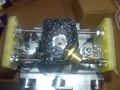
Support 3 (better): fixed block Having the heater block fixed is also a variant. Probably best available option. Heater block can have 2 stainless steel screws (M3) passing through it (above resistors) and these screws being fixed onto the 2 long vertical screws at 90degree angle, with both top and bottom nuts and some plate insulator in between each sides. This way the heater block should be totally fixed, and the thermal barrier would dilate towards towards the extruder plate instead, and probably have minimal stress if done right. All threads have to be of A2-A4 Stainless Steel, for both low thermal conductivity and strength. I have not tried regular thread but dont think they can be used on either accounts. The M3 SS threaded rods should of been dressed up in a silicone tubing as a sort of insulation, but i thought of that too late. In the picture the horizontal threaded rods are M3 and vertical ones are M4 and fixed onto carriage, and again all stainless steel threaded rods. The link between them is made with a small corner piece and a stack of 3 sheets of pcb material (FR4 or alike). I added the fan in the pictures, but it cant work like that, e.g. cools the heater block too much. Like that, with 5v pwm on fan and pushed 14v on resistor the heater cant get over 175C. In order to have fan useable the block needs some better insulation and fan needs a duct to avoid cooling heater directly. But if the top plate is aluminium then passive cooling is quite more than enough already. I intended to have the fan mounted to blow on the workpiece instead controlled with SF Cool module, although pictures dont show that. Also in the end i also pressed the copper teeth down, in the PTFE groove, so it will get also a fix there. Maybe plastic's high pressure or just simply tightening the nozzle can unscrew the PTFE, which in my case is not forced in, but only reasonable tightened by hand. Finally one important thing, the block needs to line up with the PTFE perfectly, which is fairly hard to do in practice, and if PTFE doesnt fit properly then it may either leak or get damaged.
Alternative miscelaneous materials

Yet other materials, possible replacements of the "typical" ones, to use with reprap for different purposes:
- RTV gasket silicone, its the silicone that can be found virtually at any gas station; it is used as a gasket fill between the engine block and top of the block with the valves. It stands ~350C or so, usually black or red color. I used it to cover the entire heater block (if used like that it might fume for a while when first heating). I dont really have a clue about what temperature exchange is between it and surrounding air, but i guess it cant be higher than with the bare metal exposed. I also used it to cover the underneath of heated bed, so less heat would go towards bottom. Here it also can be used to fix the thermocouple or the thermistor on heater block. It dries fairly fast and it its kinda more rigid than the typical sanitary silicone, and gets a fairly good grip on many materials. If it doesnt stick well sandpaper the surface it might help it adhere. Its cheap. Probably can be used in several other ways too. Silicone is generally given shape, before it "hardens" with the finger dipped in liquid soap, but a little saliva can do the trick aswell - e.g. keeping the silicone from sticking to the finger. I guess it depends how pervert one is ^^ - i use my saliva, but i will never disclose exactly what finger i use!
- Huge heating conduct gasket, the types used in steam heating conducts - street lines type. If you seen a big metal pipe that has like 20 big bolts around it, this is the stuff that comes in between: the old (classical) type at least, maybe now there are some other new materials who knows. Are gaskets like 20-50 cm diameter, and minimum 4-5 mm thick: usually made by a mix of graphite, asbestos and other insulating materials. Unlike advanced plastics, these are true termal insulators, especially older type ones. Usually have refractory properties up to 500C or 750C. A rectangle of this material can be put between the heater block and the heater block. Also this is fairly hard material. Cut in a small strip, i used this as retainer on the thermal barrier. Sort of instead of PEEK. At approx 230C after quite some time, the other side of the material has around 70C. This material should also be available in plate shape, prior to be cut round to fit the pipes. I had a very very old plate, dont really know where exactly to source it today, but must be some ways.
- High temperature woven tubing, covered with silicone, the type that is generally used in electronics to cover wires exposed to heat. The silicone type is somewhat elastic. Tubing that can be cut in length, and basically used as a bandage to cover the heater block or to insulate other things, with silicone on it. Its resistant and tough - imo way better than ceramic tape for any purpose. Strange enough, the silicone coating, once ignited, burns very well by itself (is this supposed to be fire resistant?), and when its done burning, remove the ashes and the woven material inside remains clear and can be used at much higher temperatures. I used the woven material soaked and filled with heat transfer compound to "dress up" the first resistors i had on the heater block, but after that i got bored and covered them in kapton as i started to believe that kapton probably has better heat transfer than previous situation. Kapton is easier and presumably better, but in the lack of, this can be a good variant also.
- Asbestos fiber or products - pure asbestos fiber is very fragile and its fibers become easily "airborn". If breathed it fixes into the lungs and probably stays there forever, even millenias later some antropologist will examine ones chest cavity bones and may find it. This way asbestos gives a specific disease (Asbestosis) and afaik it is untreatable and pretty deadly. I think this is the reason why asbestos is not used anymore, at least at the scale it used to be - in spite of its super insulation properties. Bottom line, fiber asbestos is not a material to be used in a place that is "shaken" all the time (like hot end movements), not around childrens (which are specifically susceptible to lungs issues e.g. astma, etc). Some "protection" advices around the net are just stupid. This is not the case. This is very much, far more serious. Be aware.
Considerations
Advantages
- thread on the outer perimeter of the thermal barrier can be made much bigger (M10-12-14) thus being much more robust than the variations that use a thread inside the PTFE;
- interchangeable nozzle(s) "on-the-fly";
- does not really need machined parts (except the thermal barrier that needs to be center drilled and threaded - preferably without changing the position - "in same catch")
Disadvantages
- increasing the "PTFE" part height will increase the amount of dilatation and that might need to be dealt with in terms of dilatation along z axis; not to mention the price of the piece itself;
- as a heater block made from brass is fairly heavy, and with all the "giggling" of a reprap, it might put additional stress on the thermal barrier and its thread; so probably best would be to use aluminium for heater block;
- no definite way to support it; so it needs a little "creativity" with the materials at hand;
Critical aspects
- the PTFE thread needs a slow chamfer instead of ending abruptly, if it ends abruptly, tightening it pulls thread back and thus it can easily crack it. In general tightening threads can create impressive forces and as such, the PTFE can easily get damaged simply by tightening it room temperature. Tighten by hand only, gentle, and dont overdo it. Its probably best if the PTFE thread is not tightened all the way till its end, basically stop it a rotation or half of rotation before the thread ends - this way no extra shear forces will be acting on its teeths, and wont get damaged in this way. A PTFE thread cant be treated like a metal thread. And of course a tightening failure like that will only show up later when PTFE gets hot and is tested for prints. Until then it might not even be visible.
- this is generic for all hot ends, the hole in the PTFE needs to be a little bigger than the filament + tolerance; E.g. to use a 3.0mm filament, the hole in the PTFE in my experience should to be ~3.2 (generic and pla) or ~3.5mm (especially for abs which swells more). This will impact directly on the required force to extrude (motor drive). Note that filaments measures typically 2.8 or 2.9, but some others are 3.0 precisely.
- susceptible to "leaking": the 2 threads should be done "by the book" and PTFE plumbing tape should be applied generously;
- should be no distance between the PTFE thread end and the nozzle thread start. Too much space here in the melting area might trap air (which cant go anywhere) and so increases oozing by alot (pressurized air acting like a spring will require high settings for retract or even make it ineffective). Therefore PTFE and nozzle needs to be tight against each other, at mounting with minimal or no distance in between; also the inner diameter of the nozzle where the plastic has to enter, that shouldnt be too big either for same reason. Simply put, the melted filament needs to be able to "push" all air out before starting to extrude.
dismantling
air inside: PTFE and nozzle pieces not kissing each other
fixed: PTFE and nozzle pieces now meet each other


Effects to be determined
- melting area seems smaller than other hot end styles: measured on an used used barrel the melting point seems to be right near the PTFE thread area.
- dilatation effects around the thread:
a) if dilatation of the thermal barrier is bigger than the material used as heater, it will strengthen the joint, otherwise the opposite might be valid
b) suspicion: on the long term (if it gets there), the repeated thermal stress on the PTFE expansion might result it the blobbing on the outside near the PTFE exit from the thread, near the heater block, reducing the mass of PTFE inside the hole little by little and pulling it out (so maybe a small pressure applied the opposite way with a spring might counter-act this locally, or a diameter increase would help, or both)
- thermal barrier going inside the heater block: the melt zone changes, effect to be determined;
- remains to be determined if M10x1.5mm thread on the outside of PTFE is strong enough, or other thread types should be considered;
Further changes
Heater heats up the PTFE and the melt zone is like 5 mm inside it (at the PTFE threaded area). Could try making one step further: moving the nozzle thread inside the PTFE, overlapping the 2 threads. Will have to test to see if moving the nozzle up inside PTFE is worth anything (might shorten the transition zone a little although it might just move it up).
Related Links
http://www.reprap.org/wiki/Extruder_Nozzle_Variations#DIY_Direct_hot_end_.28gas_nozzle.29
http://www.reprap.org/wiki/Gas_nozzle_hot_end