Duet
Release status: working

| Description | Duet - Arduino Due Compatible 3D Printer Electronics
|
| License | CERN OHL
|
| Author | |
| Contributors | |
| Based-on | |
| Categories | |
| CAD Models | |
| External Link |
Note for 2nd Generation Duets (Duet Wifi, Duet Ethernet) check www.duet3d.com
The first generation Duets that this page details were developed by Andy and Tony from Think3dPrint3d in conjunction with RepRapPro and with much advice from Chris Palmer (Nophead)
The Duet is a 3D Printer controller board that is compatible with the Arduino Due. This 3D Printer controller combines the 32 bits Arduino Due microcontroller with 4 (v0.6) or 5 (v0.8.5) stepper motor drivers, Ethernet, Hi-Speed SD card slot and more.
Contents
Overview
The Duet runs the 32 bit, ARM core Atmel SAM3X8E microprocessor, as found on the Arduino Due. This is a step change from preceding controllers using 8 bit microprocessors and leaves loads of overhead to do cool things (like running a web-server or running delta bots much faster). The Duet comes with Ethernet built in allowing it to run as a network printer controller, along with USB and an SD card (fully SD 2.0 compliant). The Duet 0.8.5 version update supports an additional extruder, so it can be used with both dual and single extruder printers (5 axes control). In addition it takes the Duex4 expansion board which adds a further 4 stepper channels - for a total of 9 axes controls (3 axis + 5 extruders for example). A more in-depth description of the original design can be found in this blog post. The v0.8.5 update is described here. Another expansion "shield" for two drives was distributed by RepRapPro (only for Duet 0.6).
In addition to 3D printer, this board can be used to control a laser cutter [1] [2] [3]
The PanelDue is a compatible colour graphics touch screen control panel. The Duet can also be controlled over Wi-Fi as described here.
See also Duet design.
Wiring
See dedicated pages Duet Wiring and Duet pinout.

Hardware
General
All connectors are now Molex KK type, with lock and polarization.
Board is built with four layers, including a complete ground plane, which allow good thermal dissipation and reduce noise and ground loops.
Biggest thermal dissipation came from the bottom of the board, which shall be taken into account while establishing the cooling flow.
Processor voltage is 3.3V and inputs are not protected, so using sensor with higher voltage need reliable protection. Optocoupler or diode protection may be more reliable than voltage dividers.
Specifications [4]
- Maximum acceptable voltage for stepper drivers and capacitors is 35V, the PMV40UN2 fets used on the fans are rated to 30V, so the max VIN in 30V. Boards were tested at 24V and may be safe for a stable supply up to 30V.
- Stepper driver A4982 are designed for a maximum current of 2A, with a really usable current depending from the board cooling. Board was tested with 0.8A without cooling and 1.5A on all drivers with good cooling. Drivers have a thermal safety.
- Stepper driver current is adjusted by program, using a specific G-code.
- Microstepping is locked to 1/16. Board throughput is always sufficient to handle it, including on 0.9° steppers.
- On board 5v is supplied by a buck converter with ultimate current of 2A, however the 3.3V is taken from this 5V supply, so the available 5V current (for fans or small wifi router) shall take into account the 3.3V consumption of the board and other 3.3V accessories (sensors and control panel).
- Micro-SD card type SDHC, to be formatted in FAT32, cluster size 32 kB.
- Ethernet sustained transfer speed came from 100 kB/sec to 900 kB/sec depending SD card quality and file size. You may experience faster speed with larger files. [5]
- Direct connection of mechanical switches to endstop inputs is reliable with shielded or twisted cables.
Dimensions
Size 123 x 100mm, hole spacing 115 x 92mm Ethernet plug, micro-SD slot and mini USB plug are on one small side. For 0.8.5 version, the reset and erase buttons are also on same side (they were on board face on 0.6 version). There is no plug for power supply, but a terminal block on the side opposed to plugs. 5V could be from internal converter or external supply, with pins aside the power supply terminal block.
The export from KiCAD shows the board (V 0.8.5) and hole dimensions:

Drive numbers
Drive number for G-Code commands (M569 & others) 0:X; 1:Y; 2:Z; 3:E0; 4:E1; 5:E2; 6:E3; 7:E4; 8:E5
Ethernet
The Ethernet connection is handled natively by the SAM3X8E processor, allowing much higher speed than boards handling Ethernet connection through serial link to the processor. In practice, the throughput is only limited by the SD card performance. Printing with web interface being done from the SD card, this improve usability for large files.
Open hardware license
The Duet hardware design is licensed under the CERN OHW License 1.2: the design is free to be distributed and modified within the terms of this license. All the design files are available on Github. The Duet was completely designed using the Open Source software package KiCAD so hacking and building on this design is accessible to all.
Pins/output references correspond to the references used for Arduino Due, see schematic.
Software
The Duet runs RepRap Firmware, initiated by Adrian Bowyer, which was initially designed for it. The software can receive G-Code from the USB serial port, the SD card and the Ethernet interface.
Its philosophy is everything is done with G-code, including all configuration and it use an extended set of G-codes.
Configuration file is read on SD card at start-up. Interactive configuration with immediate feedback is possible.
A pre-compiled version of the firmware is supplied with each new release. Average user never have to compile the program and does not need any development tool.
SD image shall be copied on SD-card and macros may be adapted for a given configuration.
When Duet board is connected via Ethernet, any Ethernet or WiFi device having access to your network can operate the printer with a web interface.
Recent firmware can be updated with simple file uploading over the network.
The software is evolving constantly. The dc42 and ChrisHamm forks includes Delta and CoreXY printer support.
Older versions

Duet v0.6
The Duet version 0.6 was the first issue of Duet board (in december 2013) and is still available. It combines the Arduino Due microcontroller with 4 stepper motor controllers to control a single extruder printer. Together with the Duex4 expansion board it allows for a total of 5 extruders or up to 8 axis drives. The dimensions are the same as version 0.8.5, however connector position is slightly different.
Wiring
See dedicated pages Duet Wiring and Duet pinout.

Minor changes have been made to the Duex4 resulting in version 0.2a, as detailed in this blog post: http://blog.think3dprint3d.com/2015/04/duex4-v02a-minor-updates.html link Duex4 v02a minor updates]
Issues and gotchas of v0.6 boards
The following are not intended to put you off using a Duet, indeed some other electronics boards have much worse issues.
- USB connector soldering
- The Mini USB A/B connector has 4 metal lugs that need to be soldered to secure the connector to the board. Manufacturers of Duet boards sometimes don't get this right, probably because through-hole components are typically wave-soldered from the underside, but the USB connector lugs really need to be soldered from the top. Therefore, when you receive a Duet, check that the USB connector lugs are securely soldered from the top. Duet 0.8.5 boards and Duet WiFi boards from Think3DPrint3D should not have this problem.
- On-board 5V switching regulator
- This produces excessive EMI to meet CE regulations in a complete printer without shielding. If the EMI produced by the switching regulator is unacceptable, leave it disabled (by leaving JP9 open) and provide 5V power via the external 5V connector instead. In practice, the EMI is unlikely to cause problems, e.g. it can only be heard on an FM radio if the radio is tuned to a very weak station and placed very close to an unshielded Duet. The Duet 0.8.5 has a modified switching regulator circuit designed to produce less EMI, and the Duet WiFi should produce even less.
- SD card
- The board and firmware are a little fussy in respect of the SD card specifications. A Class 4 or Class 10 card with a capacity of 4Gb to 16Gb is recommended. The file upload speed obtained via the web interface depends a lot on the card, and isn't necessarily any better with Class 10 cards than with Class 4 cards.
- Extruder heater and thermistor connector
- On boards that use header strips for the I/O connections, this is a 6-pin header strip that uses 4 pins (two paralleled pairs) to provide power to the hot end heater, and 2 pins to connect the thermistor. If you plug the 4-pin heater connector into the wrong end of the 6-pin strip, you will feed 12V into the thermistor input, and destroy the microcontroller. More recent boards use 4- and 2-pin Molex connectors instead to reduce the risk of mis-connection. The Duet 0.8.5 and Duet WiFi separate the thermistor connectors from the hot end heater connectors completely.
- ATX PS_ON output
- If the PS_ON output is used to turn off an ATX power supply, and this results in all power being removed from the Duet, then as the Duet powers down it produces a glitch on PS_ON. This may result in the ATX PSU turning on again. One fix is to power the Duet's 5V rail from the +5VSB output of the ATX PSU so that the board does not power down. Another is to add a 3.3K or 4.7K pulldown resistor between the gate and source terminals of TR7. This resistor is already included on the Duet 0.8.5 and Duet WiFi.
- Effect of shorting the +3.3V rail to ground
- If you short the 3.3V rail to ground (for example, by connecting 2-pin endstop switches to the wrong pins on the 3-pin connectors), or by wiring an intelligent Z probe with the +3.3V and ground wires reversed), then the Duet will typically be unharmed; but all heater outputs will turn on while the short persists. The Duet WiFi has additional circuitry to turn the heaters off when there is a short between +3.3V and ground.
Where to get it
- Think3DPrint3D (UK) Duet 0.8.5, Duex4 & PanelDue with screen 4.3", cable looms.
- Filastruder (USA) Duet 0.8.5, Duex4 & PanelDue with screen 4.3"
- builda3dprinter.eu (The Netherlands) Duet 0.8.5 and PanelDue with screen 4.3"
- emaker.io (UK) Duet 0.6 and 2 drives shield (only for Duet 0.6)
- Replikeo Duet (China) Duet 0.6 clone
- Escher 3D (UK) PanelDue without screen
- RepRap Ltd Duet shield (2 drives)for Duet 0.6
- kurzschluss Small extension board for Pololu drivers
Gallery
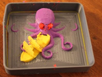
Here is a picture of a 4 colour print from the Duet and Duex4 expansion board combo...
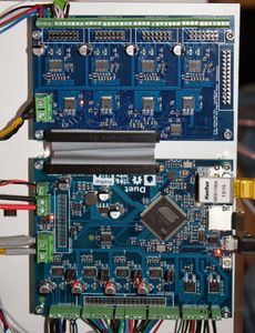
... and a picture of the set-up.


History

This is the Duet development electronics Adrian Bowyer used when he started writing RepRap Firmware while the Duet was first being designed.
There's an Arduino Due on the left feeding into a stripboard to shift levels to/from 3V3 from/to 5V in the middle. That feeds into a stripboard pretend-ATmega644P-chip in a Sanguinololu on the right. The whole thing drove a Mendel.
It was screwed to the back of a short length of skirting board.
Resources
Support
- General support: RepRap forum: Duet http://forums.reprap.org/list.php?416 or the Ormerod forum http://forums.reprap.org/list.php?340 (most of the thousands of Duet boards in the field are in Ormerods)
Hardware
- Duet 0.8.5 schematic:https://github.com/T3P3/Duet/blob/master/Duet0.8.5/Duet0.8.5_Schematic.pdf
- Duet 0.6 schematic: https://github.com/reprappro/Duet/blob/master/Duet/Duet_06_Schematic.pdf
- Duet / Duex4 expansion header pin mapping and usage Duet pinout
- Wiring and commissioning a Duet on a delta: https://miscsolutions.wordpress.com/2015/01/04/upgrading-the-mini-kossel-to-duet-electronics-part-1-hardware/
- PanelDue to Duet wiring: https://miscsolutions.wordpress.com/paneldue/
Firmware
- RepRapFirmware
- RepRap Firmware FAQ
- RepRap Firmware G-Codes
- RepRapFirmware Configuration & commissioning
References
- ↑ Laser cutter on RepRap forum
- ↑ Laser cutter on RepRap forum
- ↑ Laser cutter blog post
- ↑ Designer/manufacturer don't supply specifications, so data came from component datasheets and user experience and is for information only.
- ↑ RepRap forum thread about Ethernet speed transfer
Further reading
- Official Think3DPrint3D documentation
- RepRap forum: Duet
- Comparison of Electronics
- list of electronics
- Impressions:Duet vs Smoothie A thorough comparison between these boards - on SeemeCNC forum
In addition to site licence GFDL1.2, this page is also released under license CC BY-SA 4.0