ExtruderMechanicalParts
Making the non-rapid-prototyped mechanical parts for the Version 1.1 extruder
Introduction

There are two main mechanical parts to the extruder: the heated barrel, and the drive screw. Two small bearings are also needed for the gearing. This page tells you how to make them. The bearings are at the top (A). The parts of the heated barrel are the PTFE cylinder (D), the nozzle (B), and the M6 brass studding (C) in the middle. The drive screw is the M6 threaded rod at the bottom (E), the steel flexible coupling (F) and the drive studding (G) and the M6 nuts that fit on it (H).
The .dxf engineering drawing files for the parts are in the repository here. These were created using Qcad.
The drive screw

This should be made from M6 brass or steel studding. If you want to work with hard plastics like polylactic acid and ABS use steel. Brass is fine for softer materials like polycaprolactone and HDPE.
The screw drive consists of a 70mm length of this with two 3mm diameter bearing lands turned on it. At the top end is a 3mm hole in which is soldered a length of 3mm braided steel wire. At the other end of the wire is a 10mm length of the studding with two nuts soldered to it. This engages with the geared drive.
Start by cutting the 53 mm length of 3mm braided steel wire. The steel in this is hard, and is also easy to damage if you use a shearing cutting device. By far the best way to cut it is with a cutting disc in a mini-drill as in the picture.
Gently offer each end of the wire up to the flat of the cutting disk and rotate it between your fingers to grind a slight reduced diameter about 10mm long on either end until the ends fit snugly into a 3mm drilled hole.
This will make it much easier to solder the wire when the time comes.
Next make the drive screw. This is most easily done in a lathe, but Vik has an alternative that is described here.
This is the drawing of the two parts that you will make:

This is easiest to make out of brass, and that is an ideal material if you will be extruding a softer polymer like polycaprolactone or HDPE. For harder plastics like polylactic acid and ABS make this part from steel.
Cut a 90mm length of M6 studding. Start by drilling the 3mm hole in one end using a drill in the tail stock (don't forget to use a centre drill to get the alignment right first). Drill the 3mm hole deep enough so that you can remove the short 10mm length shown floating on the right with a parting-off tool and still have enough left for the main screw. Use coolant/lubricant while turning if you are making this from steel; brass can be turned dry. Drill the hole with a woodpecker cycle (that is, withdraw the bit after cutting every few mm to clear the swarf).
After you have parted off the 10mm section, clean the 3mm holes, then put a little solder flux in them to stop them oxidising, especially if you use steel. Next, turn the length of the remaining studding down to 70mm. Clean any burrs from the drilled holes by twisting a larger diameter drill in them. Check that a nut will still screw cleanly onto the ends of the threads and, if necessary, clean them up too.
Next turn down the bearing lands. These need to be 3mm in diameter. This will probably be easiest if you turn the job round in the lathe chuck so that you always have a the shortest possible length projecting. The drawing shows the ends of these as cones; these come from using a pointed tool. If you have a parallel-sided tool you won't have these. Either shape works fine.
Now to solder the assembly together. Make sure all the parts to be soldered are clean of oxide and grease and coolant oil (wipe with methanol - methylated spirit - to clean off any grease and run a nut down the thread to clean it, and a bolt through the nuts). If you have a compressed-air line you can blow the parts clean too. It also helps to solder the parts just after you have turned and ground them - that way there is little time for an oxide film to build up on their surface. Even finger grease can cause trouble - try not to touch the bits that you are going to solder; cleanliness is everything.
Put a small quantity of flux (from plumber's suppliers) on the two reduced ends of the wire, and inside the 3mm holes in the drive and the 10mm length of drilled studding. Be vary sparing in your use of flux; too much will make a real mess and - more seriously - cause solder to go where you don't want it to.
Push the reduced-diameter ends of the wire into the 3mm holes in the pieces of studding using a twisting motion in the direction that tightens the coils of the wire.
Hold the assembly horizontally (to reduce the effect of gravity on the flow of flux and solder). Mount it softly (to avoid damaging the threads) in a vice. Heat the ends with a blowtorch, and use ordinary electronic solder to join the parts. Apply the heat gently - you only need to get the thing up to solder-melting temperature. Take the torch away from time to time and dab the end of a piece of solder on the join; when it just starts to melt, you're there. You want a good amount of solder in the join, but don't allow it to soak along the free length of the wire. If you do, its flexibility will be reduced.
Cool the soldered parts, and re-clean the 10mm long thread.
Put flux on the inside of the M6 nuts, then screw them onto the 10mm thread length so the inner face of the inner one is 33 mm from the end of the long threaded rod with the 3mm bearing lands. Again hold the assembly horizontal and solder it. Make sure the flats on the nuts line up, leaving them slightly apart if need be. Let solder flow down the gap between the nuts.
When the whole thing if cold, file off any excess solder and brass/steel from the top of the outer nut to bring it back flat. Wipe away any excess flux. Check that the wire still bends freely.
The bearings

Now for the bearings the gear drives run in. These are made from 6mm brass rod. Here is the drawing:
Drill a 3mm hole down a length of brass rod, then part-off two 11mm lengths from the resulting tube. Use a file to blunt the sharp outer edges at the ends, and hand-twist a larger drill in the holes to clean them up.
The heated barrel

This consists of a length of PTFE rod with a 3mm hole drilled down it. The end is drilled and tapped M6, and into that is screwed the barrel, which has a heating coil wrapped round it and a thermistor glued into it for measuring the temperature. On the end of that is a nozzle with a small hole that forms the extrusion orifice.
Materials
You can make the barrel and the nozzle from three possible materials: steel, brass, or aluminium. These all have advantages and disadvantages:
- Steel: advantages - cheap, widely available; disadvantages hard to machine, low thermal conductivity;
- Brass: advantages - high conductivity, easy to machine; disadvantages copper in it may react slightly with polycaprolactone polymer;
- Aluminium: advantages - high conductivity, easy to machine; disadvantages not very strong (not a serious problem - the parts are not highly stressed in operation).
The choice is up to you and what you can obtain.
The PTFE holder
Make this from 16mm diameter PTFE rod. Cut a length of this slightly too long, and face it off in the lathe to get it the right length.
The standard polymer filament that RepRap uses is 3mm in diameter. This is a common size for plastic welding rod, for example, and so is easy to obtain. However, quality control on the diameter of such rod is not all that great, and it can be oversized by one or two tenths of a mm. This will jam in a 3 mm hole, so the PTFE is drilled at 3.5 mm. The small extra gap does no harm.
Drill the 3.5mm hole right through, then drill and tap the M6 hole. A 5mm starting hole for the M6 tap works well, as PTFE is rather soft. To align the M6 tap, switch the power off to the lathe and put the tap in the tailstock. Release the tailstock so it is free to slide on the bed, then push the tap into the PTFE while turning the chuck by hand. Use a bottoming tap, not a taper one. Rotate the chuck clockwise by one turn, then back half a turn to clear the swarf. You should be able to feel when the tap reaches the bottom of the hole.
Turn the work round in the chuck, then touch a large-diameter drill on the 3mm hole just to make a small conical widening of it. Take care here - the drill will bite into the PTFE and go too deep unless you are very gentle.
Make sure the part is clean, with no loose or partly-attached bits of swarf. Any dirt left will get dragged down by the melting polymer and block the fine nozzle.
The nozzle

The RRRF store offers nozzle tips made from dome nuts, with various hole sizes. To make them yourself, the following instruction may be useful:
This is made from a short length of 8mm diameter brass rod. Start by turning the short "nose" down to a diameter of 1.5mm. Then turn the rod round and drill the tapping hole for the M6 thread. The cone tip of this hole needs to go as near as possible to the end without actually breaking through. This is because the resistance of the device to the flow of the polymer increases markedly as the length of the fine diameter hole in the end increases - you want to keep that as short as possible. A good way to get the depth right is to offer up the drill to the outside of the device and to set it to the right position by eye, and to put sticking tape round the drill where the end of the rod is. Then drill to the tape.
Tap the thread using a bottoming tap to get it as deep as possible. Align the tap and the work either in the chuck and tail-stock of a lathe or in a pillar drill with the rod in the drill vice aligned vertically. If you try to do the thread-tapping free-hand it won't be exactly square unless you are very skilled. Turn off the power to the lathe or drill, and turn the chuck by hand to tap the thread.
Finally drill the nozzle hole. You can try a variety of diameters, depending on the size of small drill you can find. About 0.4mm works well. The finer the hole, the better the detail the RepRap machine can resolve, but the slower it lays down the material. Drill the fine hole from the inside outwards. That way the cone-tip of the thread hole will align the smaller drill at the centre.
The brass barrel

Simply drill a 3mm hole right through a 45mm length of M6 studding. Drill the hole with a woodpecker cycle (that is, withdraw the bit after cutting every few mm to clear the swarf). Once again, remove any burrs and clean away all swarf scrupulously.
The fact that the plastic filament that is being fed through the extruder may be slightly over 3 mm in size does not matter for the 3 mm barrel hole; the polymer is molten all the way down it, and for a mm or two above it in the PTFE as well.
The oversized filament problem doesn't affect the brass barrel - the plasic will be molten all the way down it...
File a notch in the barrel at 36mm (between where the nichrome coil and the nozzle will go) to glue the thermistor in. File the notch with a small rat-tail file taking care not to go all the way through to the 3 mm hole...

Next, cut an 8 ohm length of insulated 0.2mm nichrome wire. With that diameter the length for 8 ohms will be about 200mm, but the resistance is more important than the length, so cut to get the 8 ohms, not the 200mm.
Wrap the wire into the thread as shown in the picture, leaving the wire ends free (about 20 mm lengths) and securing them with Blu-tack or sticky tape. Make sure that the winding starts just after the thermistor notch and is clear of where the PTFE will go. You may find it easier to wind with the barrel still in the PTFE to hold it. The free ends of the nichrome should be at the PTFE end.

It is a good idea to glue both the coil and the thermistor at the same time. This shows the whole assembly - barrel, nichrome wire, and thermistor - ready to glue held in a clamp.
Mix up some JB Weld high-temperature epoxy glue and apply it carefully to the coil:
Then put the barrel back in the vice, put a little JB Weld in the notch, and position the thermistor. Put more JB Weld over the top of it.
Leave the glue to set for 24 hours.
But They Don't Sell JB Weld Here
If No JB Weld is available, obtain a can of black BBQ paint such as Dulux Spraykote. These silicone-based enamels are good up to 650C, but need to be dried and heated to approximately 250C to fire the enamel. Apply 3 coats under the coil, and 4 coats over the coil. A hair-dryer will speed drying and an oven or (for a really quick firing) blowtorch can be used for the final curing.
<div class="thumb tright"></div> Don't forget to mask off the thread at the ends for attaching the PTFE and nozzle!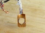
BBQ Paint is not good for attaching the thermistor. Instead of fixing it directly to the barrel or nozzle, make a copper bracket from a flattened scrap of copper piping that will securely slip onto the barrel, put a channel in it and wedge the thermistor in with a little silicone heatsink compound as in the photo on the right.
Final assembly and wiring

Do a final thorough clean of all three components - any dirt in them will block the nozzle.
Screw the three components together. Wind a little PTFE plumber's tape round the barrel before you screw on the nozzle to seal it. Also wind PTFE tape round the thread that will go into the 16mm PTFE rod. Take great care that the tape does not protrude over the ends and so partially obscure the 3mm through hole.
Do the assembly up tight, but not so tight that you damage the thread in the 16mm PTFE rod, which is quite soft.
After I screwed the barrel in the PTFE rod, but before I screwed on the nozzle, I ran a clean long-series 3mm drill down the 3mm hole between my fingers to remove any final residue and swarf, then blew it through.
Strip the insulation from the last 10mm of the ends of the nichrome wire. The insulation is glass fibre, so the easiest way to do this is to scrape it with a sharp blade at right angles to the wire.
Now to solder up the connections. Cut a 70mm length of thin 4-way ribbon cable. Split this into two pairs for about the last 30 mm. Split the ends of the pairs to make a couple of snake tongues.
Strip the insulation back by 5mm on one pair (the thermistor) and 10 mm on the other (the nichrome heater). Tin all four ends with solder.
Now here's a problem. Solder won't wet nichrome. However, if you take a short length of stiff wire (a lead cut from a resistor or capacitor works well) you can twist the ends of the nichrome and the ends of the ribbon cable round that and solder the lot - this seems to make a good join. Insulate the join with heat-shrink sleeve.
The short pieces of nichrome get hot in operation, so keep them flying free (that is, don't fold them tight against the barrel or the PTFE).
Cut the ends of the thermistor wires to about 5mm and tin them. Thread short lengths of heat shrink onto the ends of the ribbon cable, solder the ends to the thermistor, then slide the heatshrink down and shrink it.
Finally split the other end of the ribbon and strip the four ends. Solder a 4-way piece of 2.54mm-pitch pin strip on the end to make a little plug, using heat shrink to insulate the soldered joins.
Use a multimeter to check that the resistance of the coil is about 8 ohms, that the resistance of the thermistor is about 100K (or the appropriate value if you have chosen a different thermistor) and that neither are shorted to the barrel.