Geared Nema17 Extruder V0.5
Release status: Experimental
Wade has superseded this design with his more recent masterpiece which we named:
Wade's Geared Extruder.
If you're reading this, you want to build of them instead.  :D
--Sebastien Bailard 03:59, 20 November 2010 (UTC)
This is a work in progress, and any feedback is very welcome.
My Repraps, both Darwins and Mendels are all currently limited by the speed and reliabilty of my extruder. I use a Mk II Extruder for most of my printing, as it has proven to be the most reliable, but it won't extrude much above 3 mm^3/s of ABS or PLA. My goal is to try and build a reliable, printed extruder that can extrude at least 6 mm^3/s, and with luck, more.
I have built several direct drive pinch wheel extruders, but none have yet had enough torque to extrude at 3 mm^3/s, so I decided to backtrack a bit and try for a more robust extruder design.
Contents
Mechanical Description
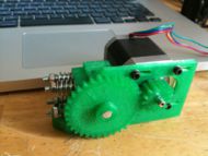
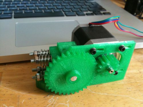
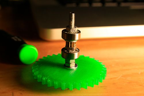
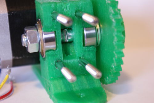
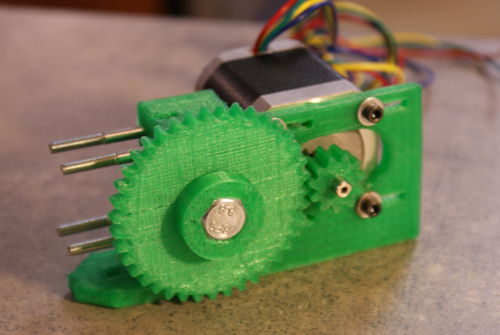
This extruder is a variation on Adrian's geared Nema 14 extruder, as well as some details gleaned from Nophead's blog. The motor is a Kysan Nema 17, 5 kg*cm holding torque. The gear ratio is currently 33:14, which isn't a huge reduction, but it does help quite a bit. It also allows me to use a very small pinch wheel, a 7 mm OD, 11 tooth gear, mounted on an M4 bolt. This has the advantage of a very small radius, reducing the torque required, but introduces significant variability in the feed rate, due to the small number of teeth. Two 624 ZZ ball bearings are used to support the driven shaft, and a third 624 ZZ is used as the pinch wheel.
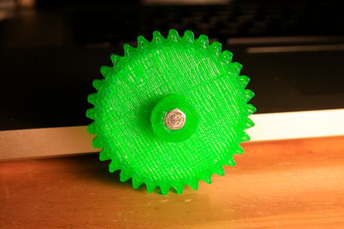
The driven axle is simply a long M4 bolt; the driven gear has a 7mm hex socket to transfer the torque, and 5mm of extra hub to help hold the gear perpendicular to the axle. You can see the teeth are a bit rough; my initial attempt used square teeth, but they tend to catch on each other. These gears were generated by Emachineshops.com's involute gear generator, then edited in Alibre Design, exported to STL, Skeinforged, then printed. My printer is a bit slow on the comms yet, so curved parts with a lot of short moves end up with too much plastic, just like these gear teeth did. However, the errors are repeatable, so my gears seem to work acceptably for now. Hopefully this extruder will allow me to upgrade to some faster firmware on my Repraps.
Test Jig
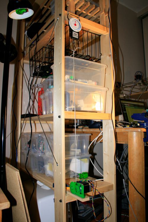
Finally, I whipped up a simple test jig using my spare parts shelves, a clamp, some kite line, and a fishing scale.
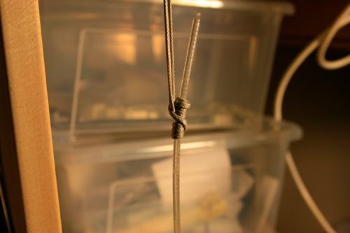
Prusik knots are cool, and strong as hell. Especially when tied with 650lb kite line. I'm not sure, but it feels like the PLA will snap before the knot slips. It's very easy to adjust too.
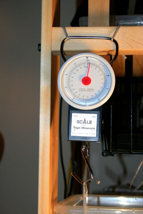
Cheapo fish scale does the trick! More kite line to hold it all together...
Results
So, end result - 5.5 kg of force before the pinch wheel started slipping on the filament. I was pleasantly surprised; I thought the printed gears or the hub of the driven gear would give out fairly quickly, but so far so good. I tightened the pinch springs about as tight as I dared, so the next step will be to try and build a hobbed pinchwheel along the lines of Nophead's. According to Nop's excellent blog, I think I may need around 7 kg of force to hit 6 mm^3/s of ABS, but that of course depends a lot on the geometry of my extruder's hot end.
CAD Files
Here's a zip of my working directory. I used Alibre Design to model the parts, as it's user interface was the closest fit for my twisted wetware. Alibre has a free trial version that will let you edit parts indefinitely, but there are limitations on the number of parts you can use in an assembly.
I wouldn't recommend building this yet, as there are some interference issues with the mounting holes, and there are a few changes to be made yet.
File:Geared Nema17 Extruder.zip
Here's the extruder re-done in Solidworks by jbayless, for SolidWorks users. File:Geared Nema17 Extruder SW.zip
Updated Results
A new version of this extruder using an M8 bolt worked much better.
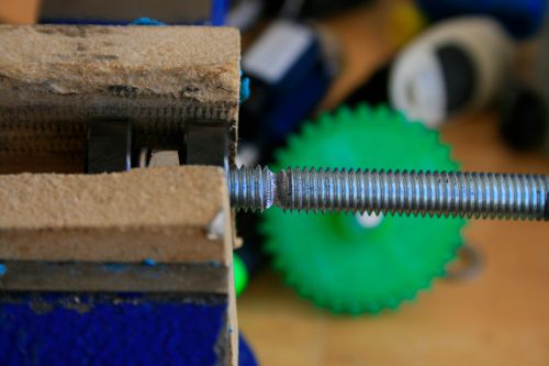
My original attempt used some M8 threaded rod, but lacking a lathe, I wasn't able to get the hobbing perfectly concentric, so it was still a bit rough.
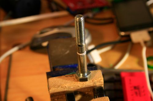
The second attempt with an M8 shoulder bolt worked much better. I used a hand drill and a file to cut the slot, then hobbed it with an M3 tap mounted in the drill, using bearings mounted in a vise to let the bolt spin (video 1 and video 2): video using File:Pinchwheelwormdrilljig.zip
So far so good!
Here's the test jig:
V2 of the M8 drive hit 16 kg - here's the results:
M8 shoulder bolt - 7.0kg,
adjusted tension, new springs - 11.0 kg,
Tightened springs, 3 trials:
15.5 kg, 16.5 kg, 15.25 kg
The final failure mode was the stepper running in reverse, as opposed to the filament slipping. That's quite promising.
Updated CAD Files
Here's the design files for the latest version:
Extruder body and idler block: File:M8 Extruder 3.zip
11 tooth drive gear and 39 tooth M8 hub driven gear: File:M8 Gears.zip
Finally, here's a spreadsheet to help calculate the proper feedrates:
