Mattroberts' Compact Geared Extruder
Release status: Working
| Description | Compact Geared Extruder
|
| License | |
| Author | |
| Contributors | |
| Based-on | |
| Categories | |
| CAD Models | |
| External Link |
Contents
Introduction
This page describes a compact extruder, similar to Wade's Geared Extruder and Adrian's Geared Extruder
Features
- Small size compared with both Adrian's and Wade's designs.
- Torque transmitted by M3 set screws / bolts, so low stress on reprap gears.
- Uses 624 bearings, and M4x40mm cap screws - the same as the rest of Mendel.
- Gear ratio of 9:31 - the co-prime number of teeth mean even wear.
- Easy to disassemble / remove from carriage.
What you need
- 1x each of the non-gear RP parts (except, possibly, base.stl)
- 1x matching pair of the gear RP parts (either drive_gear.stl and driven_gear.stl or helcial_drive_gear.stl and helical_driven_gear.stl)
- 3x 624 bearings
- 5x M4x40mm bolts (1 used for the drive shaft, the other 4 used for attaching the idle block)
- 3x M4x16mm bolts (1 used to attach the motor_mount.stl to base.stl, the other 2 used to attach base.stl to the carriage)
- 13x M4 washers
- 6x M4 nuts
- 3x M4 nyloc nuts
- 5x M3x10mm bolts (3 used to attach the motor, 2 used to attach bearing_mount.stl to base.stl)
- 2x M3 washers
- 2x M3 nyloc nuts
- 4x M3 set screws - I made mine by cutting some M3 bolts with a dremel (1 used to attach drive_gear.stl to the motor, the other 3 used to attach driven_gear.stl to the M4 bolt)
- 4x M3 nuts
If you have built a Mendel, you will have plenty of the correct size nuts, bolts and washers. The stl files describing the RP parts are contained, along with OpenSCAD source code, in the zip file: File:Mattroberts compact extruder.zip.
Construction / Drive Shaft
The construction is fairly easy - the openscad source file will generate an assembled extruder for you to look at. The hardest bit is building the drive shaft.
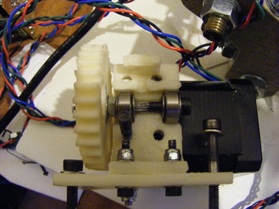
When the drive shaft is built, it should look something like this:
I used an M7x1.0mm tap to hob the bolt to provide drive to the plastic.
The order of things on the drive shaft (from left ot right) is:
| M4 nyloc | M4 washer | driven gear | M4 nut (within gear) | M4 nut (locked to previous nut) | M4 washer | 624 bearing | M4 washer | hobbed gap | M4 washer | 624 bearing | M4 washer | bolt head |
Depending on your hot-end, you will need to edit base.stl. But as you can see it is currently a 2D object, so you can easily create any mounting you want.
Modifications
You could use an M4 hex bolt with the gear the other way around to provide drive - then you wouldn't need the the two M4 locked nuts.
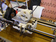
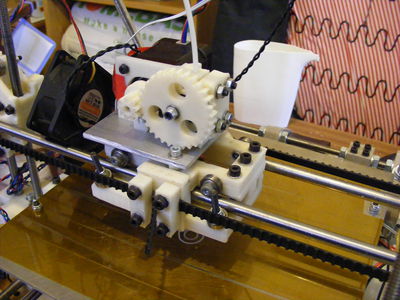
If you have a stainless steel hot end / thermal break, it makes sense to replace base.stl with alluminium, combining the heatsink with the extruder base. This works and can be seen in the main photo.
The source file contains a 'low warp' option (tested and works), and an option to use MR84 bearings for the drive shaft (untested).
Helical Gears
I've recently replaced the gears on my extruder with helical ones (to reduce noise), I've added the new gears to the zip file. Theoretically, a concern with helical gears is that they create trust sideways (which is why herringbone gears exist). My experience is that the washers and bearings are more than up to the job of resisting that trust.
License
I have made use of Greg Frost's involute gear script thingiverse, that file is licensed under the GPL license. All the other files are licensed under the creative commons (cc-by-3.0) licence.


