Metal Gear System Extruder
Release status: Working
| Description | Nema 17 Extruder Drive with metal gears
|
| License | GPLv3
|
| Author | |
| Contributors | |
| Based-on | |
| Categories | |
| CAD Models | |
| External Link |
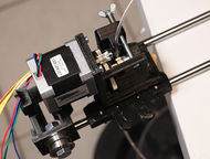
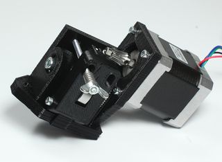
This is an extruder drive that gears a Nema 17 stepper down using machined gears. Accepts many hotends that are mounted by groovemount.
| Quantity | Description | Type | Comments |
|---|---|---|---|
| 1 | Module 0.5 gear with 80 teeth | Gears | Maedler Item no. 21108000 ; needs set screw added |
| 1 | Module 0.5 gear with 14 teeth | Gears | Conrad item 213918 |
| 1 | Module 0.5 gear with 20 teeth | Gears | Conrad item 213977 ; drives the filament |
| 1 | 608 bearing | Bearings | |
| 2 | 625 bearings | Bearings | |
| 1 | M8x20 grub screw | Hardware | For idler, alternatively use a piece of 20mm M8 threaded rod |
| 1 | M4x60 Hex head | Hardware | |
| 1 | M5x40 | Hardware | Gear shaft, use a grindstone to make a flat side |
| 1 | M4 wing nut | Hardware | |
| 2 | Washer A5,3 | Hardware | |
| 3 | M3x10 | Hardware | Motor mount |
| 2 | M3x20 | Hardware | X carriage mount |
| 1 | M3x25 | Hardware | Hinge mount |
| 3 | M3 nut | Hardware | |
| 1 | Spring | Spring | You will need a fairly strong spring (about 40-50N) that fits on a M4 bolt and is about 12-15mm long. |
Assembly
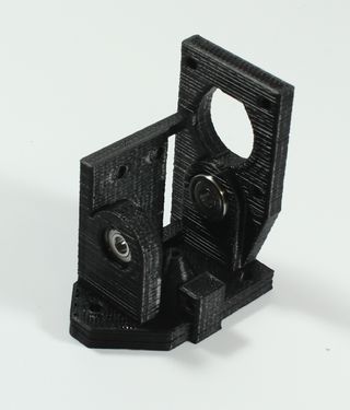
- Before assembly, drill out the filament channel hole with a 3,2mm or 3,5mm drill. Test if your filament goes through it easily.
- Push the two small 625ZZ bearings into the slots
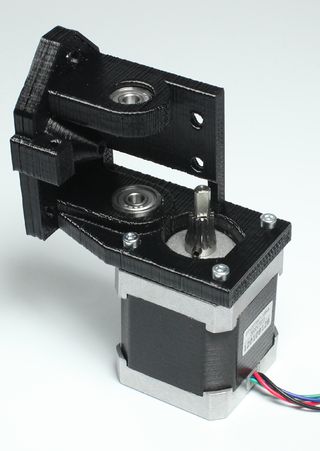
- Attach the stepper motor using 3x M3x10 bolts. Slide on the small 14 teeth gear onto the motor shaft, with the bigger side facing towards the motor, but don't tighten it yet.
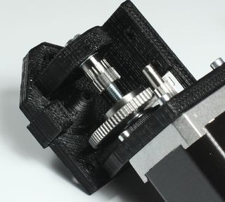
- Find the M4x40 bolt, slide it in the 625 bearing from the left. Add: A5,3 washer, 20 teeth gear (teeth side facing away from the bearing), big 80 teeth gear (with the gear side facing towards the wall where the stepper motor is mounted), A5,3 washer. Put the washer on the big gear before you begin and face the motor side up.
- Move the gear on the motor to a position where it fully engages the big gear. Tighten the grub screw.
- When the bolt is fully inserted, you need to tighten the grub screws on the gears. Push each gear towards its next bearing to ensure they don't have any play along the axis. When happy, tighten the grub screws really well. Threadlocker is recommended.
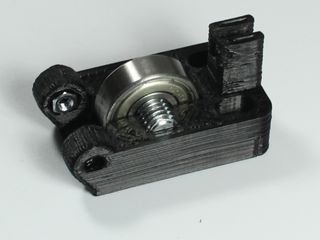
- Push a M3 nut into the hexagonal slot on the Idler, slide the 608 bearing on the M8x20 grub screw and push it into the idler
- Mount the Idler onto the extruder body by a M3x25 bolt. Don't tighten it too much, make sure it can move freely along the hinge.
- Slide the M4x60 bolt through one of the hole on the wall opposite to the idler. Slide it through the idler, add the spring and the wing nut.
Calibration
esteps per mm are calculated by knowing
- the steps per rotation of the stepper (R)
- the microstepping setting of the controller (M)
- the ratio of the gearing (G)
- the final diameter of the drive (D)
assuming 1.8 degree stepper R = 200
assuming 16 microsteps M = 16
assuming the gearing is as follows: 14 teeth initial drive, turns an 80 tooth gear G = 14/80 = 0.175
assuming the final drive as measured D = 11 (note that more pressure will force the filament to run slightly closer to the centre, so some tweaking may be required for materials of different hardness)
assuming Pi = 3.1415926
E Steps should be
R * M /G / Pi / D = 200 * 16 / .175 / 11 / 3.1415926 = 529.1385 steps per mm
this can then be fine tuned using a 0.95 fill calibration pyramid (0.95 fills should have lines, 1 fill should be solid)
