Microstepping with optical feedback
Release status: Experimental

| Description | Microstepping with optical feedback
|
| License | unknown
|
| Author | |
| Contributors | |
| Based-on | |
| Categories | |
| CAD Models | |
| External Link |
The idea is to make a module that is a functional substitute for a 400 step stepper motor and a "dumb" stepper driver board. Stepper motors with fewer than 400 steps per rotation are easy to find as surplus equipment, either by themselves, or in old computer printers. Optical encoder strips and quadrature optical encoders are easy to get from junk ink-jet printers. In order to allow retrofitting of existing systems, it is desirable to have a setup that can take the PULSE and DIRECTION command signals usually accepted by stepper motor driver boards. These items can be combined to make high precision motion control setup that is quite useful. (Similar ideas can be applied to DC motors -- see RepRapServo 1 0).
Such a system can potentially give high precision positioning even when built from low-cost, low-precision parts -- see Bamboo Printer.
Contents
Interface to G-code interpreter
My intent was to make this setup act like a stepper motor driver board, which it does. Because the step signal (PULSE) is being sampled by firmware, I have a simple pulse stretcher circuit that makes the pulses a little longer. I am using reprap-gen3-firmware-2009-08-05 (slightly tweaked) on the Arduino that generates the step and direction pulses. It makes 5 microsecond step pulses. This is a bit fast for my approx 30 KHz interrupt to detect reliably.
Stepper motor
This is a NEMA 17 motor on one axis, and larger cylindrical stepper on the other axis.
Drive Circuit
The drive circuit uses a L298. I was pleasantly suprised that I could run it at about 30 KHz, but it seems to be working fine. This is connected directly to the stepper motor in a bipolar configuration. There is no output filtering on this signal, but I have not had EMI problems.

Schematic

Feedback Loop
This system is a little different from a servo loop with a DC motor. If you put a voltage across the terminals of a DC motor, it revs up to a certain speed and will continue to rotate at that speed while the voltage is present. If you put voltages on the terminals of a stepper motor, it moves to a certain position, and then holds that position. This actually makes things easier. The feedback algorithm has a feedforward term that directly increments (or decrements) the phase when a pulse is received. There is also an integral error term that adds an offset proportional to the difference between where it is and where it is supposed to be (this is added to the phase repeatedly, which is what makes it integrate).
      +---------------------------------------------+
      |                                             |
      V         +---------------------------+       |
 +-----------+  |                           |  +---------+
 |Quadrature |->|XENC +-------+   SINE-->PWM|->|         |
 |encoder    |  |  |  | Feed  |    ^        |  |         |
 +-----------+  |  V  | back  |    |        |  | Stepper |
                |  +->| algor |->PHASE      |  | Motor   |
 +-----------+  |  ^  | ithm  |    |        |  |         |
 |Stepper    |  |  |  +-------+    V        |  |         |
 |COMMAND    |->|COMMAND        COSINE-->PWM|->|         |
 |pulses     |  |        Arduino            |  +---------+
 +-----------+  +---------------------------+
Firmware
See attached file. This is an Arduino type .PDE file and can be compiled with the arduino development software. It does use a custom made interrupt routine, though.
Optical encoder
This is a quadrature optical encoder removed from a inkjet printer. It has built-in signal conditioning which means that it has digital outputs that can go directly to the arduino pins. They are also strong enough to drive a pair of diagnostic LEDs. These let you check the alignment of the optical strip. I use the optical strip from the same printer as the encoder, since the encoder is optimized for a certain stripe spacing.
http://objects.reprap.org/wiki/Optical_encoders_01
Features
This was worth the trouble to make for the following reasons:
- Stepper motor slips (missed steps) are immediately corrected. This means that I can use a smaller stepper than I would have otherwise been able to. It also means that I don't find an overnight print with a sideways slip in the middle of it.
- The stepper is a lot quieter. This is because it is being driven with smoothly varying sinewaves, not abrupt square waves.
- The stepper runs cooler. I am running a unipolar stepper in a bipolar way. This is not a unique advantage of this technique, I know, but it is an improvement in the way that I was doing things before.
Downloads
Photos and Drawings
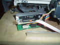
Front view of circuit board
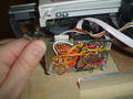
bottom of circuit board

Other Optical Feedback Projects
Ben Weiss' masters Mech E thesis was on "Closed-Loop Control of a 3D Printer Gantry" ([digital.lib.washington.edu/researchworks/bitstream/handle/1773/26048/Weiss_washington_0250O_13644.pdf pdf]).
He added linear encoders and independent controllers (based on teensy) to the x- and y-axes of a makerbot-style printer (MBot CUBE). His thesis contains detailed information about the background and implementation of his mod, including circuit and mechanical diagrams, and he has posted source code for his specialized single-axis drivers to github, as well as a modified marlin firmware to work with them.
Project overview here (can't add external links yet): sites.google.com/site/benweisspublic/projects/imc-closed-loop-control
From his thesis:
The Master Controller code runs on a standard Arduino Mega (1280 ADK or 2560), which is outfitted with a normal RAMPS shield. The Axis Controller runs on a PJRC Teensy 3.0/3.1. A wiring schematic is available in the Schematic folder of the Closed Loop Axis Controller codebase. The actual sensor used is an AMS AS5311 with 0.5um precision. A carrier board was designed by Matthew Sorensen and is available here, and follows closely the documentation in the AMS datasheet.
He concludes:
Even though attempts to implement complex controllers failed, a simple PI [proportional-integration] controller, roughly tuned, showed performance improvements that reduce path tracking error in circle and star trajectories by more than 40%, cut print time by up to 25% by increasing acceleration rate with only minimal loss of accuracy, and detected and recovered from skipped steps in a matter of millimeters. Further development and better tuning of the control algorithm should result in further improvements.
Also, his thesis provides lots of information on certain key Marlin firmware variables that aren't well documented elsewhere, such as movement speed, print speed, acceleration change (jerk), and cornering speed. If you are messing with those variables, check out his work.
Marlin and Sailfish both support varying acceleration and include code that could dynamically adjust the acceleration rate so that diagonal moves accelerate faster (both X and Y motors can share the torque load when accelerating diagonally), but the way the code is written this dynamic acceleration is only available if a_axis < a_max < sqrt(2*a_axis), where a_axis is the axis maximum acceleration and a_max is the system maximum acceleration. This kind of configuration is suggested neither in the documentation nor in Sailfish or Marlin firmware defaults. The accelerations reported in this section are a = min(a_axis, a_max).


Locally hosted copy of his thesis: File:2014 Weiss Closed-Loop Control of a 3D Printer Gantry Fig 12.pdf