OpenY
Release status: Working
| Description | lighter, easier to assemble, bearing-based y axis for the Mendel
|
| License | GPL
|
| Author | |
| Contributors | |
| Based-on | |
| Categories | |
| CAD Models | |
| External Link |
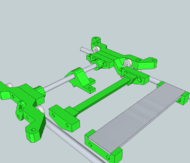
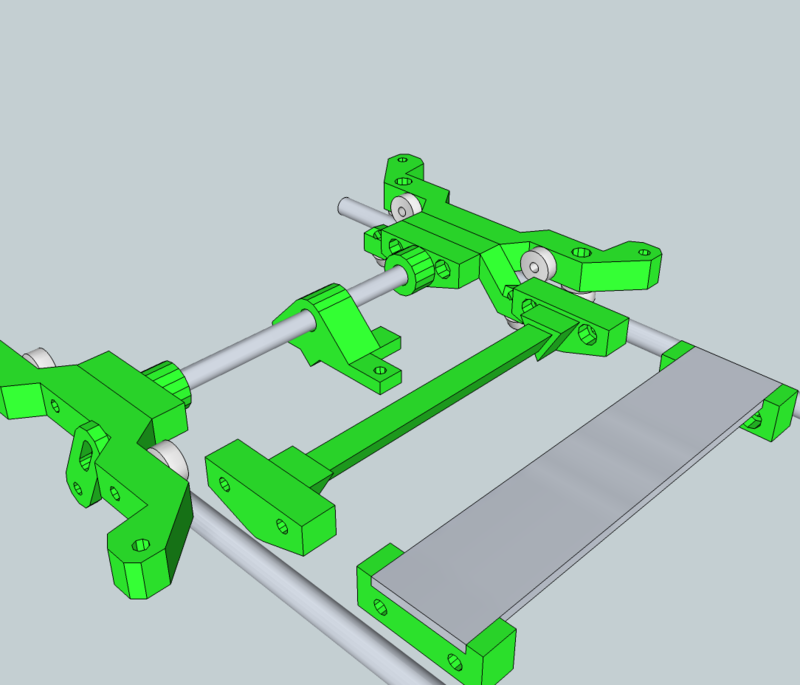
This is a complete redesign of the Y carriage. I wanted to make a lighter, simpler design while still maintaining the functionality and compatibility of the regular Sells Mendel carriage. This design works, and works well, but is still in flux and so can be considered a beta release. It will only take a couple hours to print, and will probably take you longer to unmount the regular carriage than it will to assemble and install the OpenY carriage.
Advantages
- Much Much Lighter
- Easier to assemble
- Many Fewer screws/nuts/washers
- No Squashed frog
- Can be attached/removed without removing the Y rails
- Easily adaptable and reconfigurable
Contents
BOM
Reused RP Parts
- 4 x Y Bed springs
New RP Parts
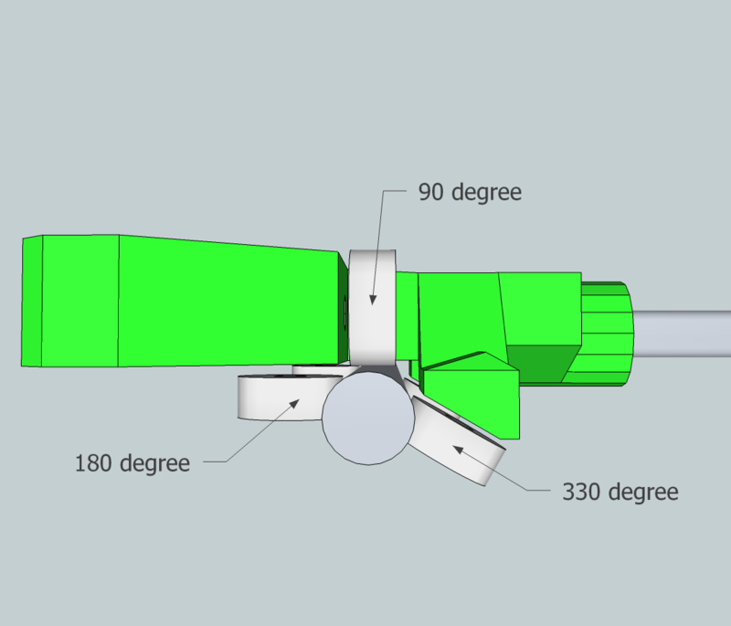
- 1 x X- Arm (90 - 180 degree bearings)
- 1 x X+ Arm (90 - 270 degree bearings)
- 1 x Inner Arm (330 degree bearing
- 2 x 8mm Mounting Bracket
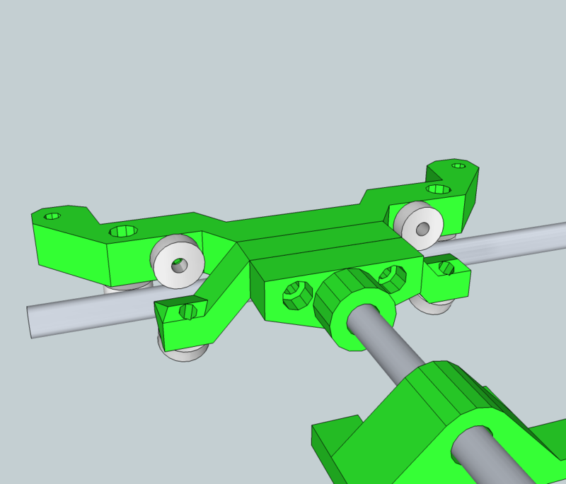
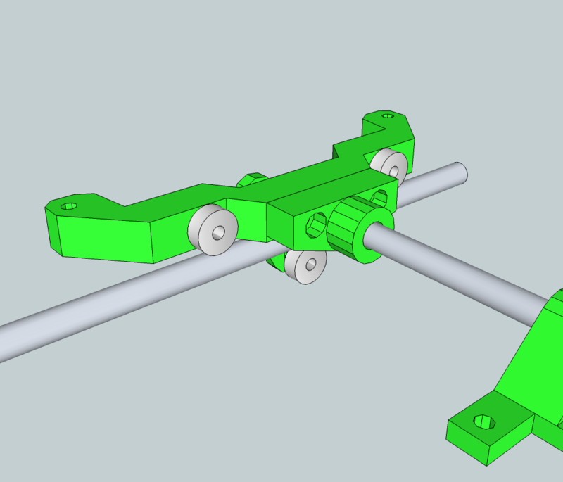
- 1 x 8mm belt and optoflag harness
- 1 x Undercarriage Bracket
Nuts and Bolts, Standard Parts
- 4 x M4-16 screws
- 13 x M4-40 screws
- 18 x M4 nuts
- ~30-60? x M4 washers
- 9 x 624 Ball Bearings
- 1 x 8mm Rod or Tube 140mm in length (I recommend a pencil)
- 1 x a package of zip ties/cable ties
- 1 x Y-Axis opto flag (you'll probably need to cut a new flag)
Assembly
I've renamed some of the parts, hoping to make the instructions clearer. The BOM reflects these changes, but I still need to update the zip files and thingiverse.
X- Side
This is the side that will be closest to the X axis motor, hence X- (negative). First, attach all the 624 bearings.
Put a bearing on each end of the inner arm using M4-16 screws. you can use a washer on each side of the bearing, but you can probably get away with only one washer between the bearing and the plastic. You probably will not be able to get a washer on the nut side.
Next put the bearings on the X- arm. The X- arm is different from the X+ arm in that it has more holes. Use M4-16's for the 180 bearings, and make sure you put the screw in so that the head is recessed, or else it won't be long enough. You'll have to use M4-40 screws for the 90 degree bearings, but make sure the head is on the inside, against the bearing, or else the screw will hit the nut on the inner arm.
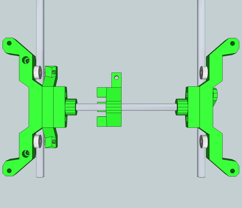
with all the bearings attached, sandwich the three components together, with M4-40 screws, in this order (x- arm)>(Inner arm)>(8mm mounting bracket). The final piece looks like a leaping frog. test the fit of this assembly on your Y-axis rails, and add or remove washers until you get the best fit possible. This assembly is really the key for how well constrained the y axis is, so spend the time now to fine-tune it.
X+ Side
attach the two 90 degree bearings just as you did on the X- arm. This side has only 2 parts to sandwich, so you'll need to add some extra washers to the M4-40 screws because the M4 nut will reach the unthreaded part of the screw before tightening down.
Carriage assembly
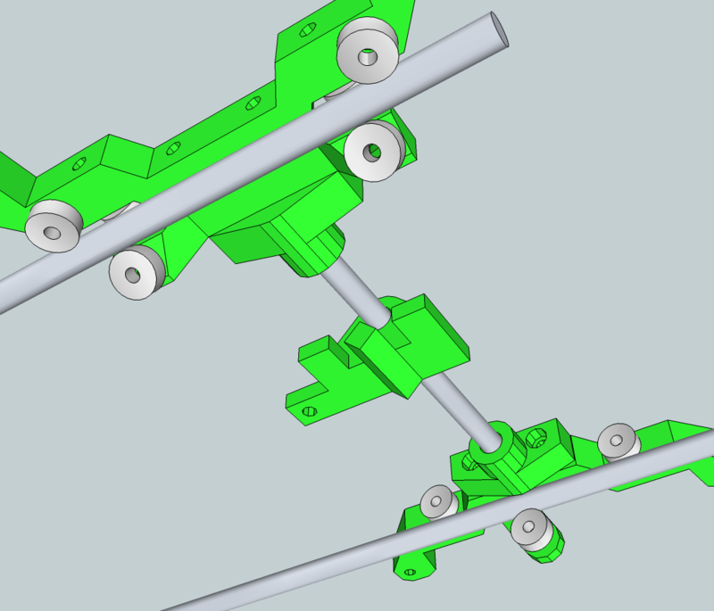
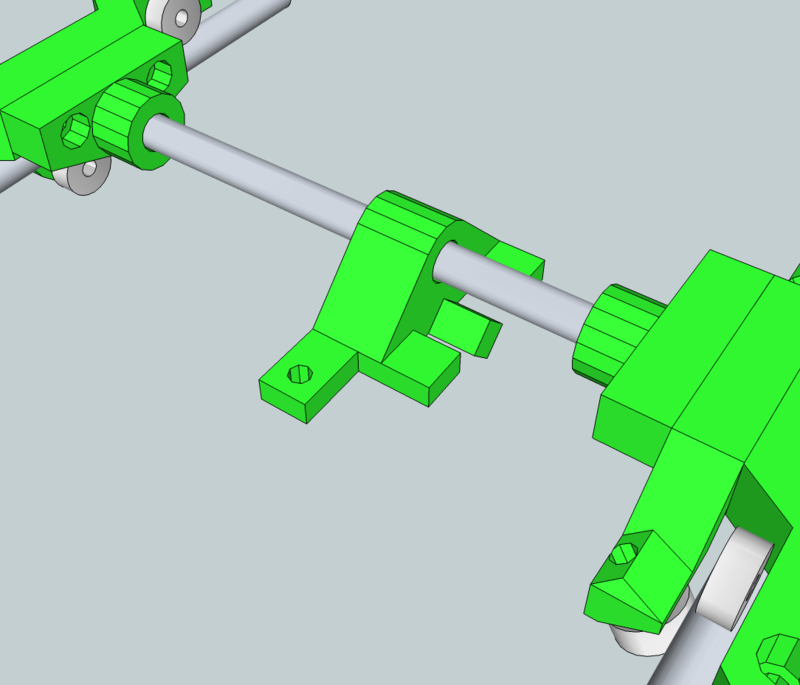
Attach the optoflag onto the belt harness. Next, slide the belt harness onto the cross-member (the 8mm rod or whatever you are using). stick one end of the crossmember into the X- side, and the other end into the X+ side. Pay attention to where the Opto endstop is!
Attaching the Bed and Mounting the Carriage
use the regular bed springs and 4 M4-40 screws to attach the bed to the mounting points on the carriage. Hold the assembled bed above the Y axis rails and slide the belt harness into the approximate right place, in line with the belt.
The X- side will 'Clip' onto the Y rail with some downward pressure. Realize that if you turn the mendel upside down at this point, the bed will pivot around the attached y rail, which is why you need the undercarriage bracket.
The undercarriage bracket goes over one of the 'sandwiching' screws. first, add the bearing. I needed many washers in order to get the bearing to line up with the bottom of the rail, so just keep adding washers (M4-40 screw) until it is in the right place. put a washer on the sandwiching screw (I used the one closer to the Y motor), then the undercarriage bracket, then another washer, and then the nut. when you tighten the nut, it will torque the bracket upwards when you tighten it, cinching it against the bottom of the rail.
Since this part is a bit hard to get to, you can put a zip tie over the end of the undercarriage bracket screw and the end of the other sandwiching screw. when tightened, it will hold it securely against the rail.
Attaching and Tensioning the Belt
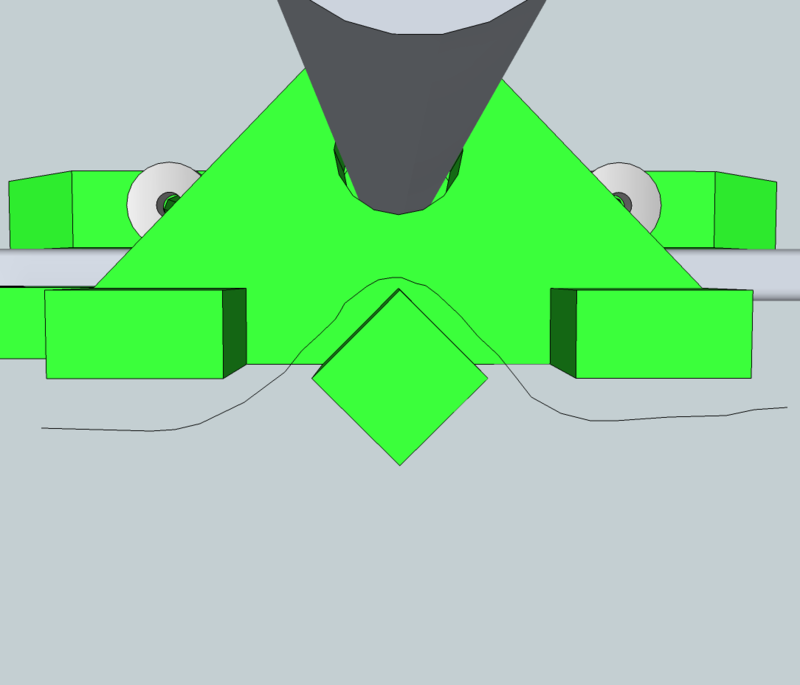
The Belt is fed through the teeth of the mounting harness like in the following crude render:
Put loops in the ends of the belt, and secure them with zip ties. put a zip tie through the two end loops and cinch it down, tensioning the belt.
the best place for the connecting zip tie is either right at the harness (if attaching it to the top run of the belt). you can also put the connecting zip tie on the bottom run, but you first have to put the Y carriage in the center of the rails, and then line up the belt ends so that they meet, or come close to meeting, directly opposite of the belt/optoflag harness. if you don't do this right, the belt ends and zip ties will either go into the motor or the idler, and either skip steps or just make annoying noise.
Pictures and Files
Files
Files are up on thingiverse, or you can grab the zip file up in the infobox
Edit:8mm_Belt_and_Flag_Harness
Variations
There are a number of different variations i have designed. I'll post them all eventually, but just list them for now.
- A fully RP crossmember (triangular cross-section) with accompanying mounts and belt/flag harness
- A mount for a flat bar crossmember, 30mm wide. maybe if you want to use particle board or MDF, or aluminum bar?
- Separate Optoflag and belt harnesses. I think development will probably eventually go this way, as I'm going to try to find a better place to put the endstop. if i find a better place, then the optoflag holder would be for compatibility with the regular design.
Future development
I also thought up some ideas for improvements, and have gotten some good suggestions for improvements from the community.
- A way to tighten the 180 and 330 bearings onto the rails. currently, if it's way too loose, maybe from warping, you need to adjust a sketchup file and reprint something
- a new bed leveling adjustment that can be adjusted from the side of the carriage, so changes can be made quickly without moving the machine, or using two tools.
- heated beds might need a different arrangement, with most of the RP parts below the rails. this would hopefully prevent any warping or distortion, but would require a greater redesign effort, and would probably lose the 'clip-on' ability.
- I would like to get all the parts parametric, likely through openSCAD. I've got some learning to do in that regard, but if anybody wants to start this, be my guest.
