RUG/Pennsylvania/State College/Hot Tip
Back to State College RepRap Main
Release status: unknown

Hot Tip Projects
Introduction
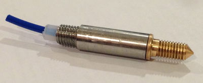
Penn State has desiged and is manufacturing their own hot extruding tips. The hot tip consists of three components: The brass tip, the steel tube, and the teflon liner. The brass tip is made from brass bar stock supplied by the class. The tip is what extrudes the filament into layers. The steel tube holds the tip in place and screws into the extruder base plate. The teflon liner is inserted into the steel tube to allow the filament to slide easily into the brass tip. Using the manufactuing abilities that are available on campus, we are able to make brass tips with nozzle sizes of .5mm and .35mm.
This page is to store and organize information on hot tip production for future students and others intersted in learing about hot tips.
We are hoping to get .25mm tips made in the near future. Students working on the hot tip project are experienceing problems using drill bits that small. The attempt to make these fine tips with the CNC Lathe in the FAME lab is currently in progress.
Files
Below are the solidwork files as well as the drawing for the hot tip. Additionally, a model of the plate used to hold the tip is included.


.
Wiring of Tips
When wiring the tips of extruders there are a few primary supplies you will need: nichrome wire, copper wire, crimps, thermocouple wire, chimney cement (tacky adhesive that is resistant to heat), Kapton tape, and painters tape.
1) Cut approximately 8-11 inches of nichrome wire and on both ends of this crimp around 5 inches of copper wire. After they are securely crimped wrap a piece of Kapton tape around the crimped points, this will hep prevent any shorting of the wires onto the metal tip.
2)Prepare the thermocouple wire by cutting approximately 6 inches, and stripping one end and twisting the two ends of the wires around one another. Check that the wire then makes a circuit using a DMM to ensure the thermocouple will work.
3)Carefully wrap the nichrome section of wire around the tip, using the threads as a seat for the wire to lay in. Wrap with the threads from the base to the tip, making sure the wire is not skipping grooves. Then on the last or second to last wrap lay in the twisted tip of the thermocouple. Wrapping in the thermocouple towards the end will help make sure it gets a good temperature reading.
4)Using painters tape, restrain the loose wires hanging off of the end of the nichrome and the remainder of the thermocouple wire to the shaft of the metal tip. This will help to hold them in place while the head cement if drying.
5)Using the head cement, cover all the wires wrapped at the tip to cover them and securely bond them to the tip. This will keep them in place and help protect them from falling off or becoming damaged.
Bowden Extruder Prototype Design
The Bowden extruder design allows the extruder body/motor to be separated from the extruder plate so that just the plate and hot tip are attached to the carriage. A long piece of Teflon then connects the hot tip and extruder.
The current prototype design was created with the intention of being able to use existing hot tips and extruder plates. The hot tip steel body has to be slightly modified by extending the external threads. This allows the steel body to protrude about 0.300" through the other side where the drilled and tapped 1/8" brass plug is attached. Then, an 1/8" brass coupling is used to connect the brass plug and Teflon quick disconnect fitting.
Brass Coupling Hex Style P/N: 50785K91
Brass Plug Solid P/N: 50785K334


Delta Bot Extruder Plates
Below are two different designs for a Delta Bot extruder plate. One design is made with a center hole diameter of 5/16" - 24 threads per inch to accept the SCRUG hot tips. The other design has a slot milled out of it to accept Nate Myer's E3D J-head style hot tip. The SolidWorks files are below.

Fame Lab CNC
The Fame Lab in Leonhard Building was nice enough to allow us to use one of their CNC turning machines. We currently do not have a standing agreement in terms of using their space but are open to allowing us to use the facility if you ask. To inquire about the CNC machines at the Fame Lab you should first contact Mike Immel and then Scott Heckman. Explain that you are working on hot tips for this class and were wondering if you can utilize a CNC turning machine.
After you get permission from Mike, you are going to be required to obtain a log-in account to the IE department network. Scott Heckman should be able to set this account up for you, but make sure to talk to Mike Immel first. Once the log-in has be obtained, the online safety videos and quizzes can be found hereand complete the FAME Lab training. Don't worry the course doesn't take too long and using the CNC is definitely worth the time and effort. If you are only using the CNC Lathe, you should only have to complete the turing center videos.
The Fame Lab does not like to provide you with tools needed for the machines, but if you ask Dan (his office is in the corner of the lab and can usually be found in the lab somewhere) to borrow the tools and talk to him nicely, he probably will. Be very careful with the tools, don't break any of them or destroy anything or they will get really mad. Make sure to clean up everything when finished.
Some hints about the Fame Lab. Make sure you know how to use mastercam or you will spend alot of time fustrated with the program and there isn't much help available from the lab guys. Make sure you know how to transfer, edit and read g code and use the lathes. NEVER trust the G code. Make sure you slow go through each line of the code and make the lathe prove that it will work. By stepping through the code slowly, you can avoid problems of crashing tools and destroying stuff.
Manufacturing
We are currently doing a combination of manual milling and CNC milling. For the brass tips we have created a CNC code so that the extruder hole and the whole outside part can be completed at one time. Then a manual lathe is used to drill the .125 hole. Both of these steps can be done in the FAME lab. The steel part can be completed in the FAME lab of the Learning Factory on the manual lathe.
Lab Safety
General Terms and Descriptions:
Axes:
y-axis - forward/ backward. Axis measurements to .001 inches (one mil).
x-axis- left/right. Big wheel.
compound axis- Adjustable angle axis. This will be used for threading and for cutting the cone on the brass part.
Gears: We use high gear and low gear. Low gear is for threading only, and high gear is for any other type of cutting. A demonstration of this should be done in person. Change gears only when the lathe is off, and change speed only when it is on.
Threading should be done at 80 RPM. For brass, cutting is done at 500 RPM. For steel, cutting is done at 500 RPM.
Tools: This refers to the different cutting tips that go on the lathe. There are four that we use: facing, for cutting a flat side; turning, for reducing the diameter; threading, for cutting threads; and grooving, for cutting a groove. There is also a drill, which is separate from these tools.
Mil: This is a unit of measure, equal to .001 inches. This is what everything will be measured in.
IMPORTANT STUFF:
BE SAFE. DON’T BE STUPID.
Always wear safety glasses inside the FAME lab. If you do not have a pair, lender pairs can be found on the wall to the left right as you walk in.
If you have any questions, don’t hesitate to ask a TA. They are pretty helpful, and they all know what they are doing.
Before you do anything, think through it. From experience, it is really easy to ruin your part, and this can be avoided by not making any silly mistakes. Make sure you are familiar with the operation of the lathe before you use it.
Some Tips and Tricks:
● When you are cutting threading, the best way to check if you are done is screw the threads into another part. Use emery cloth to sand down the threads a little bit. If you are worried about cutting to deep (especially on the steel part), you can finish the threads with a die. However, this is only for cleaning up and finishing the threads, not cutting them entirely.
● When tapping or drilling, be very liberal with the cutting fluid, and use it frequently. If something starts smoking, back out the bit and give it a minute to rest.
● Use your calipers early and often. It’s really easy to mess up the part because you didn’t measure something correctly the first time.
Steel part
Prepare Stock
1 Use the horizontal band saw to cut a piece from the bar that is ~1/8 of an inch longer than the full length of the part.
Face
2 Put the piece into the lathe, Less than half should be sticking out. Put the facing tool on the lathe.
3 Face the end of the part. Don’t take much material off, you just need a flat face.
Reduce Diameter
4 Put in the turning tool. Touch off against the end of the part (x direction) to get a zero point. Then, touch off in the y direction and enter the diameter of the part as measured with a caliper.
5 Cut down the smaller diameter (.31inch). Do this by moving in steps of ~20 mils in the y direction, then moving along the part in the x direction. Watch the indicator to know how far to go(.29inch). Make sure to check your diameter after a few times with a caliper to see how much is left to take off, as it is more accurate.
External Threads
6 Put the threading tool on the lathe. On your left is a threading chart. Make sure that the levers are set to cut at 24 threads per inch.
7 Put the lathe into low gear. Set the speed control to ~40rpm.
8 Set the compound axis to 0 degrees. There is a lot of play in the compound axis handle so make sure you approach 0 degrees turning clockwise. This will be what you use for depth of cut. The y axis is for backing away from the part only.
9 Touch off using the y axis, this is your zero point. Before each threading pass, return the y axis to the zero point.
10 Back the Y axis from the part and turn the compound axis clockwise .005 inch (5 tick marks).
11 Move the x axis about an inch to the right of the part. Move the y axis to the zero point.
12 Look at the threading indicator (a spinny thing with numbers 1-4 on it). When it gets to a line, pull up the lever below it to engage. You may want to practice this a few times before you actually cut threads into the part.
13 Let the auto-threading run until just before the tip hits the shoulder of the part. Disengage the threading lever. This will create a groove next to the shoulder called a thread relief.
14 Go through this process 5 times. Each time, move the compound axis in ~5 mils.
15 Use a 5/16 – 24 die to finish the threads. In order to test if you are finished threading, get a 5/16-24 nut and see if it fits.
Drill Center Hole
16 Move the cutting tool out of the way, and set up the drill with a centering bit. Cut a centering hole (not very deep) using plenty of cutting oil.
17 Get a drill bit size B. MEASURE THE BIT BEFORE YOU USE IT. DON’T TRUST PEOPLE TO PUT IT BACK IN THE CORRECT SPOT. Drill 1.5” into the part. Use plenty of cutting oil.
Part Cut Off
18 Put the cutoff tool into the lathe. Touch off and zero the x axis. Back out the y axis and move the x towards the chuck for the width of the cutoff tool. Re-zero the x axis. The idea here is to have the x axis read zero when the right side of the cutoff tool lines up with the right face of the part.
19 Put the lath in low gear. Turn the lath on. Turn the speed control to 120 RPM for steel.
20 Move the x axis towards the chuck until it reads the length of the part (1.29”).
21 Turn the y axis in slowly to start cutting. Take your time. If you see chips you don’t need to turn any harder.
External Threads
22 Put the machine back into high gear (lever forward, pin out).
23 Get a drill bit size I. Check its diameter. Drill out the part to more than ½ inch depth.
24 Get a tap (5/16-24) and a tap handle. With the piece still in the lathe, tap the hole. Go in 1-2 turns, then back out and spin the tap back and forth. Use lots of cutting oil, and every few turns back the tap all the way out and wipe it off. Keep going until you have tapped in about ½ inch.
You are finished making the steel part. You should check everything over to make sure its correct. Blow out the inside of the part with compressed air to clean it. If the edge is sharp, you can deburr it with the sander. If you have a finished brass part, make sure it screws in.
CNC Brass Part
For .5 mm or .35 mm
The brass part uses the HAAS lathe in the FAME lab. There is a training process that must be completed before using the FAME lab machines. After access and training are complete make sure that the lathe isn't reserved for other projects or reserve it yourself before starting.
Gcode file
This file needs to be put onto a floppy disk for the HAAS lathe. The FAME lab has floppy disks and a floppy writer if you need to use it.
Setup
Tools
1. Facing Tool OD ROUGH RIGHT - 80 DEG 
2. NO TOOL
3. Rough lathe tool OD FINISH TURNING TOOL - 35 DEG. 
4. Threading Tool OD THREAD RIGHT INSERT 
5. Narrow Cutoff OD GROOVE RIGHT - NARROW INSERT 
6. Cut-off tool 
7. NO TOOL
8. Center drill .125 dia (SPOT TOOL .25 DIA.) This tool requires a 1/8 collet that clips into the tool holder. 
9. .5mm drill (DRILL .125 DIA.) The tool name is .125 but it is the .5 mm drill size. This tool requires a small chuck to hold the bit which is held in a 1/8 collet that clips into the tool holder. 
10. NO TOOL
Material
Put the bar stock into the machine. It needs to be sticking out 1.5 inches from the chuck. The first time you may need to have it stick out a little farther and machine a flat face on the material.
Zeroing
Note: Please ask someone in the lab BEFORE beginning this procedure. It is not too difficult but a small mistake could break the tools or machine.
Each tool needs to be zeroed before running the program. This is done on the X axis by slowly moving the tool into the spinning part and machining a new diameter. Then measure the diameter and input that value into the machine. The Z axis is similar except the part is not spinning. Slowly move the tool towards the part while holding a small piece of paper between part and tool. When they are close enough that moving the paper between them gets a little tight STOP. This distance -.003" is the zero position of the tool.
Running the program
When you are ready to run the program ASK someone to run it the first time to make sure that the program works correctly the first time. After that the program should be able to run all the way through by itself. The material will need to be pulled out 1.5" after each pass.

This is the full interface of the HAS SL-20 CNC Lathe. Although it seems very intricate, once you start running the program, you only use a few of the buttons and it becomes rather easy. The pictures below explain the different sections of the interface panel.

This key pad is used to run the CNC lathe. Some of the important buttons are as follows:
In the top left: The "Reset" button is used to clear error codes, that arise, and must be pushed before any programs can be run. the "x dia measur" and "z face measur" are used when setting offset distances for the tools.
Middle Left: When the "handle jog" button on the right pad is pushed, the "-z, +z, -x, and +x" buttons choose which direction to manually move the lathe.
Bottom Left: The buttons most used were the "5% rapid, 25% rapid, 50% rapid, and 100% rapid" buttons control the speed at which the lathe moves between uses.
Middle Top: Pushing the "ofset" button allows you to set the offsets of each tool loaded into the lathe. "curnt comds" takes you to the program that is currently loaded into the lathe to be run.
Middle Middle & Middle Bottom & Bottom Right: These two key pads are used to make changes to the GCODE that is loaded into the machine.
Top Right: The "Edit" row allows you to change the GCODE. The "Single Block" button allows for one line of code to be run at a time. This is especially useful when running a program for the first time, or running a program where the tools get close to the spindle. It allows you to make sure each action works as it is supposed to at a reasonable speed. The "Coolnt" button turns the coolant on and off manually. This function can be written into the program, but sometimes it is necessary to turn it on and off manually. The "Turret Fwd" and "Turret Rev" rotate the turret when tools are being loaded or when the lathe is being used manually to select a tool. Pressing the "Handle Jog" button allows you to manually move the tools closer to the work piece. The numbers in the row are the movement sizes that can be selected for movement in the X and Z directions.

The "Power on" and "Power off" buttons are pretty self explanatory. The "Power on" button must be pushed once the main power breaker on the back of the machine is turned on. The spindle load meter displays the load applied by the machining tool on the spindle. It is not uncommon for the meter to read over 100%, this is OK. The "Emergency Stop" button can be hit to immediately stop the machine in the instance of something going wrong. Additionally, as a safety feature, the button must be pushed when turning the lathe on. The handle is used when the "handle jog" button is pushed. Rotating this knob moves the turret with the tools closer or farther away from the spindle in increments chosen from the other display. The "Cycle Start" and "Feed Hold" are used to start and pause the program. When the program is in single "block mode" pushing "cycle start" moves the program through each line of code.

This is a close up of the Display Key Pad

This is the screen that shows the program and what is running. The left side of the screen shows the GCODE of the program and which line it is on.
Manual Lathe Brass Part
1 Put the brass bar into the lathe. Face off the part.
2 The next tool you will need is the turning tool. You will machine the bottom half (the one with the cone) first.
- a You should set up a zero point at the end of the rod. Make sure you also touch off on the y axis.
3 Cut the first diameter (the side with the cone).
4 Set up the compound axis at 45 degrees. The handle should be facing away from you. The compound axis will be making the cut, which is a good check to see if it is set up correctly. 5 Make the cut with the compound axis, and take the depth of cut using the x- axis. Take very small cuts, and try to only cut in one direction (so that the bit is pushing, not pulling).
- a this part is finished when you have a sharp cone. It’s time to stop when you are no longer cutting the cone and are only shortening the piece. There isn’t really a good way to measure this, just eyeball it.
6 Cut the threading on the long end. This doesn’t actually thread into anything, it is where the nichrome wire lies. Try to make the grooves wide enough so that the wire will fit.
7 Take out the part and flip it around.
8 Using the turning tool, cut down the diameter of the back end.
- a BE REALLY CAREFUL HERE. The tool will be VERY close to the chuck on the lathe. DO NOT hit the lathe with it, you will break something. If necessary, angle the tool away a little bit so that it will not hit the lathe.
- b If you are unsure how to do this part without breaking something, please ask for help. It is a huge pain to recenter the lathe, which will have to be done if you knock it.
9 Put the grooving tool on the lathe, and cut the groove. You only need to cut one width of the tool. Depth isn’t critical, but be careful not to cut so deep that it will interfere with the hole for the filament.
10 Cut the threading. This is slightly easier than all of the other threading, because of the groove. It allows you to first stop the feeding and then back away from the part, rather than doing both at the same time.
11 Cut the hole for the filament. Make sure to use a centering bit first, then the .125 drill bit. The idea is to cut as deep as possible without actually coming out the other end. The better you do at this, the less likely someone is to break a drill bit cutting the tiny hole.
12 Congrats! You’re finished. Make sure everything fits together, and that it generally looks right. Check against another tip that has already been machined. All that’s left is to drill the .5mm hole and put in some teflon tubing.
13 The tiny hole is drilled using a chuck, centering bit, and drill bit that are from the RepRap class, not the learning factory. Please try to keep them separate. The hole is drill from the outside of the piece, not the inside. Use as high RPM as possible while still being safe (~2200). Be careful, it’s really easy to snap the drill bit, and that is bad.
For <.5mm (2012 version)
You will have to use the CNC lathe program below:
- Note: Please read section 1.5 before using the CNC lathe. In order to use the CNC lathe you must first obtain permission from the Fame Lab as complete a safety course. Information can be found in section 1.5 of this page. Please read them.
1 Load piece into CNC Lathe with 1.5" sticking out.
2 Set machine up with program, load your tools, and set your axes, as learned in FAME Lab training.
3 Start machine and let program run.
4 Clean up machine when done making all pieces.
5 Follow steps 8-13 for back-side of part.
Redesign
11.30.12 (In Progress) - We are currently working on redesigning the steel tip to include a smaller teflon piping to allow more space for the threads screwing into the hot plate. Updated solidworks drawings will be added when complete. With a smaller sized hole, we are working inserting a aluminum oxide rod to allow for higher temperature melting.