Repic
Release status: Working
| Description | "as simple as possible" all-in-one electronics based on PIC18 or PIC24
|
| License | GNU Lesser General Public License
|
| Author | |
| Contributors | |
| Based-on | |
| Categories | |
| CAD Models | |
| External Link |
"Perfection is achieved, not when there is nothing more to add, but when there is nothing left to take away." - Antoine de Saint-Exupery
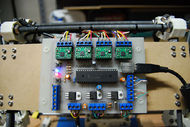
This page details the experimental all-in-one USB/PIC-based motherboard I am developing for RepRap and CNC routers. It may be of interest to programmers who are familiar with Visual Studio Express and want to play around with the RepRap firmware within that environment using a minimal set of hardware.
Please note that Repic is still in development and has not yet been fully tested. Repic is a significant departure from the standard electronics both in terms of architectural design and compatibility. I'm making it publicly available in keeping with the spirit of RepRap, but it's up to RepRap-dev and the community as a whole to decide whether any of it has any merit.
File:Repic.pdf
File:RePic2016.zip
Contents
Current Status, December 2011
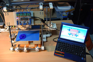
Repic is now functional and printing successfully. The code base is currently undergoing a clean-up, and usability features are being added to the host software.
Known issues:
- The heat-bed hardware has been designed but the firmware and software components have not yet been added. I'm currently undecided as to whether this should be a standard component of Repic and also whether it should remain transistor driven or use a relay instead (if you have an opinion one way or the other then I'd like to hear it).
- Stepper values can be tweaked in software but are currently stored on the host PC as user settings. This will be changed in the next release where they'll be stored on the RepRap itself, as extruder temperature currently is. The default values when the program first runs are 80/80/6720/13.5 for XYZE, respectively. Note that the E value is set to the values typically used by the RepRap software i.e. it's mm/min of extrusion. If you're using Skeinforge then you'll need to set it to mm/min of plastic rod which is a much higher value, typically around the 600 range. The Virtual RepRap component also uses the E value to do it's rendering and thusworks properly with either package.
- A minor bug in the 5D code starts the print at zero speed instead of the first value that comes along, this usually manifests itself as the head taking a few seconds to "wind up" to speed before printing begin. Doesn't affect the print any, but it will be fixed in the next version.
Design Goals
The primary design goal for Repic is to pare the electronics back to an absolute minimum. This means designing a single-sided, through-hole PCB that can be easily made at home. It also means a lowering of cost: a full set of electronics on EBay frequently sells in excess of AU$300 whereas a complete set of Repic-based electronics costs around $80, including the four Pololu stepper drivers. I am currently researching ways to safely replace the Pololus with PWM-controlled H-bridges which should bring the price down further to around $40. Another consideration is that the holy grail of RepRap is 100% replication; the more complex the hardware requirements, the longer this will take to achieve.
A secondary goal of Repic is to make it as user friendly as possible. In pursuit of this goal I have chosen to move to a USB-based hardware interface. This allows RepRap to support full plug-n-play capability as well as removing the need for a USB->serial convertor and the associated configuration headaches for the end user.
Design Issues
For the main controller of my motherboard I have replaced the Arduino-based architecture with one based on the Microchip PIC series. My current PIC of choice is the 18F4550 which has several advantages:
- Cost. At $11 per chip it's about the same as an Arduino.
- Native USB 2.0 compliancy. Development of USB client devices is extremely easy with this chip.
- Minimum support electronics required.
- Good I/O support. Up to 16 bi-directional digital endpoints, 13 10-bit A/D inputs and 1 D/A output.
- Available in both SMD and DIP packaging.
One of the disadvantages to using this chipset is that there is no freeware C++ compiler available for the PIC18 architecture (the standard RepRap firmware is written in C++). I get around the problem by running a gcode parser host-side, which means Repic cannot operate in standalone mode for the time being. I am currently in the process of designing a PIC24F based board which will in turn allow the Repic motherboard to operate in USB host mode, this will allow support for reading gcode files off the now well-established USB memstick standard thus replacing the current SD-card based system and finalizing the design of Repic as a fully USB-compliant device.
Repic Motherboard and Feature Set
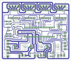
The Repic motherboard is a single-sided PCB using through-hole components only. There are no jumpers or thin traces between pins. The board contains a USB connector, plug-in slots for up to four Pololu stepper drivers and terminals for the following:
- Three microswitch endstops (although opto-endstops are also supported).
- The extruder heater and thermistor
- A PWM-controlled heatbed with thermistor. The heater coils can be run off 5V, 12V or a combination of the two.
The board also supports in-circuit programming via the USB port for firmware upgrades and general development work.
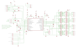
The PIC circuitry is quite basic and was loosely based on a variety of circuits around the web including those by Dan Overholt, mdhosale and "Evan". The heatpad, extruder/thermister and stepper circuitry is based on Adrian's Pololu-based circuit. A considerable amount of inspiration was also derived from Peer's simplified electronics.
Pros:
- Through-hole only, can be made at home using toner transfer method.
- Cheap! About $80 all-up, including the four Pololu drivers.
- Fewer failure points due to the simplified electronics.
- USB plug-n-play interface, i.e. no user configuration required.
Cons:
- All-in-1 fixed design means it's not flexible.
- Supports only one extruder.
- Can't run standalone.
- Windows-only host software.
Repic Host Software
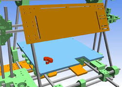
The host software is still in the very early stages of development. In addition to basic hardware testing and printing of pieces I have also implemented a "Virtual Mendel" mode that allows me to play print sequences in realtime (albeit at much higher speed) before committing them to plastic.
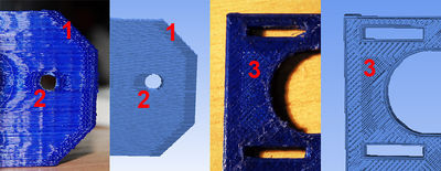
The Virtual Mendel mode is also handy for troubleshooting various hardware problems. The piece in the image below was printed by a modified Adrian's geared extruder which exhibited several minor defects including a "bunching-up" of the plastic at the edges (1 and 2) and non-uniform areas of infill in the XY plane (3). When the Virtual Mendel was run with the extrude rate set to a constant value the same artifacts appeared in the simulated output, confirming suspicions that the extruder was unable to quickly change the extrude rate due to insufficient grip on the plastic filament.
Thermistor Calibration
Thermistor calculations are based on NopHeads excellent post on the subject. I'm using one of the official thermistors with a Beta of 4066 and an R25 of 100K, and using NopHeads calculations I have selected an R1 of 4700 (which is wired in parallel to the thermistor on the extruder itself) and an R2 of 10k (which is the R6 resistor on the motherboard). At the moment these values are hard-coded into the Repic host software but in the weeks to come I'll be adding them to the configuration settings that get stored in EEPROM so that they can be set via the host software during initial commissioning.
One of the things I've noticed is that temperature readings seem to be very susceptible to the USB supply voltage; when driven from my laptop they tend to be very noisy whereas when using my dektop machine they're stable. This doesn't seem to affect extruder operation, but I'll probably need to add some software filtering to smooth things out a bit.
Extrusion Technical Details
Repic supports "FiveD" accelerated extrusion using 32-bit integer-only additions in a PIC interrupt routine that executes 10,000 times per second. Movement and feed rates are updated with an iterative integrator that implements the standard equations for uniformly accelerated linear motion, an additional term is calculated using Bresenham's line algorithm to compensate for accumulated round-off error. The net result is perfect 5D extrusion, taking G1 GCode parameters as input and generating the raw clocking signals to send to the steppers.
A complete description of the algorithm with sample code snippets is on the Repic5D page, the algorithm is very straightforward and should port easily to other low-end architectures.
Repic Project Files
Building Repic electronics involves the following steps:
- Download the PCB files and make a single-sided PCB from them.
- Load the bootloader image into the PIC18F4550. If you don't have a PIC burner then try breadboarding one (todo: create a page showing how to do this). Then install the chip onto the Repic circuit board.
- Download the Repic package below and program the Repic firmware into the microcontroller. To do this, plug Repic into the host PC (or press the reset button) while holding down the program button. Then use the Microchip HID Bootloader application to upload the firmware to the chip.
- Assemble the rest of your RepRap as normal plugging the steppers, end-stops, heater and thermistor into the appropriate terminals.
The entire Repic project package can be downloaded here:
Repic v0.4 (beta) Project Files
The package includes the following components:
- Firmware binary
- Hardware PDFs of schematic, PCB and silkscreen.
- Host software install application (Windows XP and above)
- Firmware C18 project file and source code
- Eagle project files
- Host software project, libraries and source code
If you want to modify anything then you might also need some of the following software, they're all available for free download:
- Eagle (needed to open and edit the circuit schematic and PCB project files).
- Microsoft Visual C# 2010 Express (needed to compile the WPF front-end and USB interface code).
- MPLAB IDE (needed to open the firmware project and edit settings etc).
- MPLAB C18 Compiler (needed to compile the firmware)
BOM
The following is the Bill of Materials needed to build a Repic motherboard. All of the components listed below are recommended but not all are absolutely necessary. The LEDs can be left out, since the host software will tell you when the motherboard is connected and working. The switches can be left out if you don't want to do any in-circuit programming. The terminals and sockets are included mainly for convenience, if you're happy to solder wires and stepper drivers directly into the motherboard then these aren't needed either. The "Required" field below indicates whether the component is needed for a "bare bones" version of Repic.
| Item | Description | Example supplier | Quantity | Cost per unit | Total cost | Required | Notes |
|---|---|---|---|---|---|---|---|
| - | Blank Fibreglass PCB - 150 x 150mm | Jaycar | 1 | $8.95 | $8.95 | Yes | Exact size isn't important but should be at least 12 x 10 cm (~4 1/2 x 4 inches). |
| - | Pololu stepper driver board | Pololu stepper driver board | 4 | $12.68 | $50.72 | Yes | |
| IC1 | PIC18F4550 microcontroller | RS Electronics | 1 | $12.00 | $12.00 | Yes | Jaycar sell this chip for $45 but I once managed to get them to match the RS Electronics listed price. |
| R1-R5 | 4.7K ohms resistor 5% 1/8W | Jaycar | 5 | $0.46 | $2.30 | Yes | R5 only required for a heat bed |
| R6 | 10K ohms resistor 5% 1/8W | Jaycar | 1 | $0.46 | $0.46 | Yes | Please see the section on extruder calibration for selecting a value of R6 if you're using a different thermistor to mine. |
| C1-C2 | 22pF 50V ceramic capacitor | Jaycar | 2 | $0.36 | $0.72 | Yes | |
| C3 | 0.1uF 50V electrolytic capacitor | Jaycar | 1 | $0.45 | $0.45 | Yes | |
| C4, C6, C7 | 10uF 25V electrolytic capacitor | Jaycar | 3 | $0.34 | $1.02 | Yes | C7 only required for a heat bed. |
| C5 | 0.47uF 50V electrolytic capacitor | Jaycar | 1 | $0.45 | $0.45 | Yes | |
| Q1 | 20MHz Crystal | Jaycar | 1 | $4.95 | $4.95 | Yes | |
| Q2, Q3, Q4 | VNP14NV04-E MOSFET | mouser.com | 3 | $2.23 | $6.69 | Yes | Q3 only required for 12V heat bed. Q4 only required for 5V heat bed. |
| - | 40-pin IC socket | Jaycar | 1 | $1.00 | $1.00 | No | Optional socket for IC1. |
| SV1, SV2, SV3, SV4 | SIL socket strips | RS Electronics | 3 | $4.00 (pack of 5) | $4.00 | No | |
| SW1 (RESET) , SW2 (PROGRAM) | SPST square PCB switch | Jaycar | 2 | $1.25 | $2.50 | No | Mainly used to make in-circuit programming easier during development. |
| LED1 , LED2 | 3MM LEDs | Jaycar | 2 | $0.20 | $0.40 | No | Can be any color you like, I use red (power indicator) and blue (status). |
| X1 | USB type B socket | Jaycar | 1 | $2.95 | $2.95 | No | An old USB cable can be soldered directly to the PCB as a cheap alternative. |
| X6, X7, X8, X9, X10 | 2-way PCB screw mount terminals | Jaycar | 10 | $1.20 | $12.00 | No | |
| X2, X3, X4, X5, X11 | 3-way PCB screw mount terminals | Jaycar | 6 | $1.55 | $9.30 | No |
The suppliers in the table above are all based in Australia (mainly Melbourne) with the exception of Pololu. Prices are in Australian dollars ($AUD) which at the time of writing is virtually the same as the US dollar. Electronic components are overpriced in Australia so I'll also provide the total US price which I calculated from the SparkFun list prices:
| Total Cost | $AUD | $USD |
|---|---|---|
| "Full featured" Repic: | $120.86 | $88.35 |
| "Bare bones" Repic: | $84.45 | $65.80 |
Note that most of the extra cost in the "full featured" Repic ($21.30) was spent on the very expensive PCB screw mount terminals I used. If you build the full motherboard then I'd suggest checking your local electronics store for a cheaper alternative.
Developer Contact Details
Mark Feldman (aka Myndale)
