Reprappable-inkjet
Release status: experimental
| Description | An inkjet head that can be completely made in a RepRap machine
|
| License | GPL
|
| Author | |
| Contributors | |
| Based-on | |
| Categories | |
| CAD Models | |
| External Link |
Contents
Introduction
This is an inkjet head that is completely makable in a RepRap machine. It was inspired by Johnrpm's Scratchbuilt_Piezo_Printhead.
It has only three reprapped parts. The other parts are standard easily-obtainable items. There is no machining involved in making it - the only tools needed are scissors, a scalpel or razor blade, a hammer, a short piece of 3 mm steel rod to use as a punch, and a glue gun.
It uses a piezoelectric buzzer to drive the ink.
It is experimental, so it's reliability is not yet perfect... But it does work (there's a video below).
I need to do more work on the driver electronics. Then I'll see if I can add heater elements so we can inkjet waxes and wood's metal...
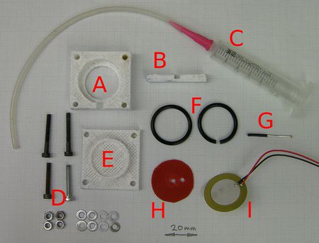
Bill of Materials
All the files for this are here in the RepRap repository.
| no. off | part | picture key |
| 1 | reprapped body | A |
| 1 | reprapped tube clamp | B |
| 1 | ink tank | C |
| 1 | length of 3mm soft silicone tube | C |
| 2 | 25 mm M3 set screws | D |
| 2 | 20 mm M3 set screws | D |
| 4 | M3 nuts | D |
| 8 | M3 washers | D |
| 1 | reprapped buzzer clamp | E |
| 2 | 25 mm O rings, minor diameter 2 mm | F |
| 1 | sewing pin with a length of wire insulation | G |
| 1 | plastic disc | H |
| 1 | 27 mm diameter piezo buzzer element | I |
The plastic disc can be cut from any reasonably stiff (but not brittle) piece of flat plastic. I used an old plastic box. Draw round the piezo buzzer element with a fine felt-tip pen then cut carefully inside your line with scissors. You want the disc and the buzzer to be the same size.
I used a syringe as my ink tank, but any small watertight container that you can connect to the silicone tube will do.
I used one of these YU87U buzzers from Maplins, but these (untried) from Mouser look as if they would also work. (Note the Mouser ones are not supplied with leads - you have to solder them on yourself.) If you want to make a smaller device (you'll have to redesign the reprapped parts) then Mouser also sell a 12 mm diameter piezo disc.
When connecting wires onto the piezo element you need to take more than the usual amount of care. Soldering to the brass disk is usually trouble free if it is clean and not placed on a cold surface. However soldering onto the silver film on the piezo disk is often a problem. In the past commercial users have resorted to using conductive epoxy to join the wires to avoid the trouble. For best results you need to have a high silver content solder, regular solder will dissolve the silvering before your eyes as you try to get your blog of solder to adhere leaving bare ceramic that you can do nothing with. You may be able to use other low temperature alloys that have a higher concentration of alloy elements besides lead and the method used by many companies is to use a spring loaded contact (often with multiple points). Using gold plated phosphor bronze connector terminals (some contacts are folded over and can be carefully unrolled to achieve a nice spring) and with suitable locations already printed into the housing may be the fastest way and allow for multiple contacts and easy exchange of the disk for testing.
Construction
The Inkjet Nozzle
You need two holes in the plastic disc: an offset one to let the ink feed tube through, and one roughly in the middle for the nozzle. I found that the easiest way to make clean holes was to put the disk on a flat piece of wood then tap a short 3mm steel rod with a sharp-edged flat end against it with a hammer. This acts as a punch, driving a clean-cut 3mm disc of plastic down into the wood. Make the tube hole so that the tube is a tight fit. The nozzle hole doesn't matter much.
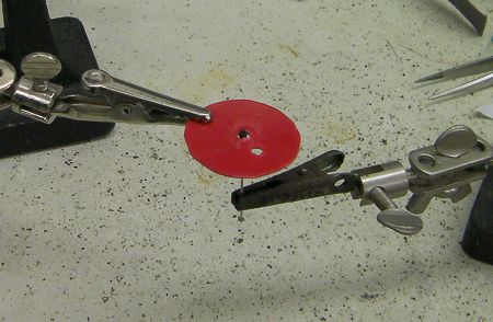
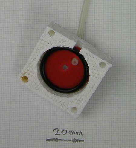
This is how I made a fine inkjet nozzle. It was surprisingly easy. I put a short length of wire insulation on a sewing pin to increase its diameter, with the pin tip sticking out by about 1 mm. I covered them very lightly with silicone grease. Then I clamped them as shown above, with the pin tip just sticking through the nozzle hole.
I dropped a blob of glue onto the pin tip from a hot glue gun. I made sure there was enough to completely cover the pin and to spread a bit over the plastic disc to stick.
Take care not to block the other hole for the tube.
When the glue had set, I pulled the pin and wire insulation out. Then, using a magnifying glass, I very carefully shaved thin slices off the top of the glue blob until I just got down to the hole made by the pin tip.
Comparing the hole under the lens with fine-diameter wire measured using digital calipers, I reckon the hole is about 100 microns in diameter.
Alternative untried methods
Use spray glue or double-sided sticky tape to make one side of the plastic disc sticky. Stick aluminium foil to it. Cut the foil round the outside of the disc so they match. Cut away the foil over the tube hole.
Place the disc and the foil foil-downwards on a hard flat surface (glass?). With the pin carefully make a very small hole in the foil roughly in the middle of the disc's nozzle hole.
Another alternative would be to pull a thin glass tube to make a fine nozzle. The problem there would be getting the pulled region short enough - you want a fine hole, but not a long fine tube leading up to it. The tube needs to be short and fat.
It may be better to glass-pull a thin solid glass cylinder to make a very fine filament, then to build up a blunt cone around that, then to use the glue-gun trick above with the cone and filament as the hole-former.
See also here.
Ink supply
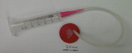
Connect up whatever you are using as a tank to the silicone tube. Put a little silicone grease on the other end of the tube and force it through the offset hole in the disc. It leads through from the nozzle hole side. That is to say: the tube leads out in the same direction that the finished inkjet will eject ink.
Make the tube project about 1 mm through the plastic disc.
Final assembly
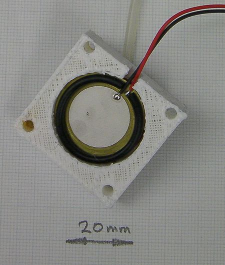
Put the what is now the nozzle disk with the tube into the reprapped body. Have the tube next to the notch.
Lightly cover one O ring with silicone grease and put it in after the disc.
Put the piezoelectric buzzer in with its active face towards you in the picture. Lead its wires out through the notch.
Use the scalpel to cut a short (about 2mm) section out of the second O ring. This will accommodate the wires. Put the cut O ring onto the piezoelectric buzzer.
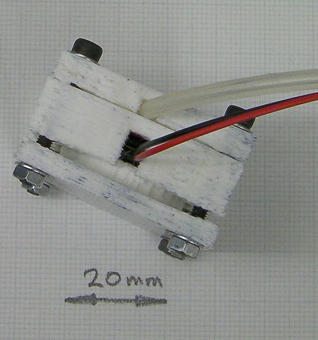
Put two washers on the 25 mm cap screws and put them through the tube clamp. Use this clamp to bend the tube through a right angle and lead it out parallel to the wires.
Put the buzzer clamp on the back of the second O ring. It has a raised annular cylinder to push down on that ring.
Use the two 20 mm screws to attach the other end of the device together.
Tighten the screws diagonally, just a turn at a time. You want the pressure to be uniform and the clamp not to be at an angle to the body.
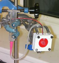
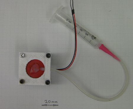
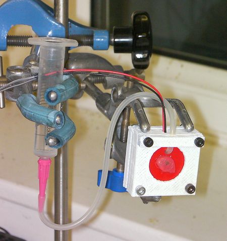
Here is a picture of the finished device.
Electronics
CAUTION The buzzer needs high voltages of the order of 100 volts to work. While experimenting, your hands will get wet with whatever you use for ink. Do try not to electrocute yourself...
This section is temporary. I'm going to do a proper driver design with a Cockcroft–Walton ladder to generate the voltages needed.
To get it working I used a MOSFET driven by an Arduino switching 12 volts into the 24 volt secondary of a small 220 volt to 24 volt mains transformer. I put a reverse-biased diode across the transformer to dump back EMF.
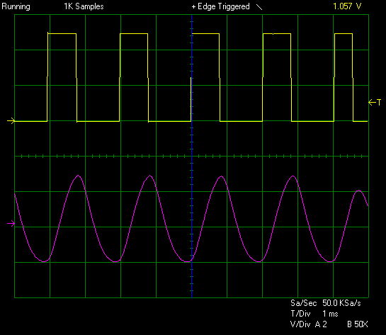
I connected the transformer primary (i.e. the mains side) to the buzzer. I drove it with a square wave with a mark time of 800 microseconds and a space time of 1200 microseconds.
I put a push button between pin 3 on the Arduino and ground to turn the pulse train on and off. Pin 2 drives the MOSFET.
Here is what is going into, and coming out of, the transformer. The top yellow trace is the output from Pin 2 of the Arduino. The bottom purple trace is the voltage across the piezo (50v/division). The transformer, being a very large inductive load, and the buzzer, being a mostly capacitive load, makes a complete mess the waveform - not much use for fine control.
Test Program
Here's the Arduino test program:
const int drivePin =  2;
const int switchPin =  3;
const int LEDPin =  13;

int MSState = LOW;
long previousM = 0;
long mark = 800;
long space = 1200;

void setup() {
  pinMode(drivePin, OUTPUT);
  pinMode(switchPin, INPUT);
  digitalWrite(switchPin, HIGH);
  pinMode(LEDPin, OUTPUT);
  previousM = micros();
  digitalWrite(drivePin, MSState);
}

void loop()
{

  unsigned long currentM = micros();

  if(!digitalRead(switchPin))
  {
    digitalWrite(LEDPin, HIGH);
    if (MSState == LOW)
    {
      if(currentM - previousM > space)
      {
        previousM = currentM;
        MSState = HIGH;
        digitalWrite(drivePin, MSState);
      }
    } else
    {
      if(currentM - previousM > mark)
      {
        previousM = currentM;
        MSState = LOW;
        digitalWrite(drivePin, MSState);
      }
    }
  } else
  {
     digitalWrite(LEDPin, LOW);
     digitalWrite(drivePin, LOW);
  }

}
Alternative untried circuits
Most buzzers are designed to mechanically resonate at the desired audio frequency. Does tuning the output frequency of the Arduino to exactly hit the resonance peak or to stay well away from the resonance peak of the piezo disk make any significant difference?
A pulse transformer has lower inductance and is expected to work better than the power transformer in the prototype.
There are several circuits that produce narrow, high-voltage pulses. nophead mentioned Wikipedia: boost converter. Daniher mentioned one particularly low-cost boost converter: camera-flash circuits [1].
Perhaps allow a relatively slow trickle of charge from the Cockcroft–Walton generator through a resistor to charge up the piezo capacitance, drawing in liquid and flexing the metal disk. Then suddenly discharge the piezo capacitance by turning on a transistor directly across the piezo capacitance, ejecting the droplet. Will this work significantly better than a pulse transformer?
Getting it working
I used tap water with a little detergent dissolved in it to reduce surface tension.
Bubbles are your enemy.
If there is any air in the ink cavity the device won't eject liquid.
Set things up so you can easily vary the head between the ink tank and the inkjet head. When the device is working you want the head only to be about 10 mm or so. But when you are setting it up you may need a greater head to force the liquid through.
With the nozzle pointing upwards, twist the device about and tap it to get all bubbles of air out of the nozzle.
When you press the button on the switch attached to the Arduino you should hear the buzzer buzz, and you should see a fine jet of liquid come out of the nozzle.
Remember that the piezo has a polarity: you want the short mark to eject the droplet and the longer space to allow refill from the tank. You may have to swap the leads to make things work.
