Tantillus
|
English • العربية • български • català • čeština • Deutsch • Ελληνικά • español • فارسی • français • hrvatski • magyar • italiano • română • 日本語 • 한국어 • lietuvių • Nederlands • norsk • polski • português • русский • Türkçe • українська • 中文(中国大陆) • 中文(台灣) • עברית • azərbaycanca • |
Release status: working

| Description | The portable self replicating mini printer
|
| License | |
| Author | |
| Contributors | |
| Based-on | |
| Categories | |
| CAD Models | |
| External Link | http://tantillus.x10host.com/Home.html (tantillus.org link is now to a domain squatter)
|
Contents
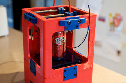
Tantillus
Introducing Tantillus. The portable self replicating compact printer.
Status
May 31, 2013
- New Tantillus settings calculator added to Tantillus.org
- Calculates extrusion widths for any given layer and hotend size.
- Calculates layer height rounding errors down to 1 nanometre.
- Calculates speed for the given layer height and object size.
- Calculates approximate temperatures for the layer height, width and speed.
February 27, 2013
- Added Cable Z axis to github repo. No lead screw wobble possible. Limited layer heights possible without large rounding errors. 0.149 is the best at 100.66 steps per mm.
June 15, 2012
- Source and production files added to github repo.
May 27, 2012
- Printed case files have been available for a couple of months on GIThub
- Case source added to GIThub May 24, 2012
- Blog entry about the cable drive.
- Blog entry about print quality.
- Case has been successfully printed in ABS by Nophead (ABS version). See below for details.
- Created RepRap forums Sub-forum for Tantillus.
May 16, 2012
- Public Beta version finalized.
- Tantillus.org launched.
- Indiegogo Campaign launched.
- 1 month until all the files are released.
Mar 28, 2012
- Beta 0.1 printed in ABS was unsuccessful due to ABS warping. A special version was designed with openings to relieve stress but it too was prone to warping and cracking in ABS.
- All parts are successful in PLA and have passed many hours of printing.
- Alpha 1.0 of laser cut version complete.
- Multiple copies of Laser cut Beta 0.1 being assembled for testing.
- Public release estimated for End of April
Feb 27, 2012
- Alpha 1 is finished and printing. Geometric Object Deposition Tool Blog
- Beta 0.1 under construction.
Feb 9, 2012
- Alpha unit assembled and ready for testing.
Design goals
   √  Portable.
   √  Commonly available parts and materials.
   √  Self replicating.
   √  Compact.
   √  Autonomous printing.
   √  Printable frame. (Printable version only)
   ≈  Expandable. (Printable frame only)
   ≈  Belt upgrades. (For those of you who just have to have belts)
   ≈  Larger version of laser cut model. (Tantillus Plus)
   ∅  Custom interface shield. (Currently hardwired)
   ∅  Dual extrusion for expanded frame and Tantillus Plus.
√ Complete | ≈ Current Development | ∅ Future Development
Specifications
Outer dimensions: Printed version
- 225mm x 225mm x 300mm
Laser cut version
- 240mm x 240mm x 300mm
Build Area:
- 100mm x 100mm x 100mm
Features
- Fully printed case.
- It can print all of its own parts.
- Designed to use J-head hotend.
- Internally mounted extruder with bowden cable.
- External power supply to allow for battery operated use.
- Uses an interesting drive train: low cost wire rope (fishing wire) or High test Braided fishing line instead of costly belts (It wraps 5 times around the rod and then goes through a hole and wraps an additional 5 times resulting in no slip). This is a roll on roll off system with a fixed anchor in the middle.

Printing the case
Please contribute to this section as you print the case
The Twelve large case parts are designed to be printed on their edges in the orientation provided.
I would not recommend printing the case with a nozzle larger than 0.5mm it has some thin areas we want to be at least two perimeters thick.
Some warping is acceptable but should be avoided if possible. The top four case parts are the most important to be square and true. Don't fret if the thin pieces around the X and Y motor mounts break. Only the top few mm of the motor mounts are critical to holding the motors, the rest being there to allow for sliding the motor down for gear installation.
The case stiffeners are designed to pull the center seams of the top of the case outwards to prevent the nuts catching on the XY ends. The nuts that hold them must be thin (my #10 nuts are 3.3mm thick). Use washers behind the stiffener to adjust the amount of force being applied to the case and use washers on the bolts that hold them on to adjust the length of the bolt to prevent it from sticking through the inside to far and contacting the XY ends. On the left and right sides, the fan mount takes the place of the washers behind the stiffeners.
The extruder should fit such that the side of the motor is barely touching the bottom lip of the case. The motor mounting holes in the extruder end have enough slack to allow the motor to be moved slightly away from the side of the case. Simply loosen the M3 motor mounting bolts, adjust the motor, and tighten the bolts again. If the motor cannot move far enough from the case edge, check that the washers used on the motor mount screws are 7mm outer diameter and not 8mm.
The build platform on the printed Tantillus may be offset to one side or the other a few mm beyond what is adjustable with the upper Z axis mount. This can cause the hotend to hit the adjustment bolts on the top platform. Consider drilling slots going along the X axis instead of holes on the lower platform for the screws attaching to the Z lift arms.
Exploded view
Click to see full size image.


PLA case
All attempts at printing the case in PLA have been successful with the exception of machine failures. See the Tantillus sub-forum to see the builds in progress.
ABS case
Special ABS version is hard to print but possible as Nophead has proven here. He managed to print Base1 and Base2 normal in ABS by rotating them on their backs, it did make the round corners harder to print but was successful. The Rest of the parts are the ABS versions. They too are a little difficult to print because I made the cutouts rounded on the tops. The Source for the ABS case is in the GIThub repo and the shapes of the cutouts can be changed with relative ease (if you are familiar with blender).

Assembling the printed case
Use #10-32 x ¼" hex cap screws and matching nuts for all connectors with the following exceptions:
- The top two holes of each of the uppermost connectors use #10-32 x ¾" with #8 washers on both sides of the stiffener (between screw & and stiffener, and between stiffener and connector)
- The right side connector uses #10-32 ¾" screws as it will also be used to hold the extruder.
- The vertical (corner) connectors use #8 x 1"
- A #10-32 3/4" screw and nut should be used in the vertical holes running between the front middle and front top pieces.
Printed parts
   (All versions)
       1   -   Carriage top
       1   -   Carriage bottom
       1   -   Bowden clamp
       2   -   XY end (left)
       2   -   XY end (right)
       1   -   Z upper bracket
       1   -   Z lower bracket
       1   -   Z motor mount
       1   -   Z lift bracket
       1   -   Z coupler (set)
       1   -   Z arm (left)
       1   -   Z arm (right)
       1   -   Extruder body
       1   -   Extruder motor mount
       1   -   Extruder idler
       1   -   Extruder large gear
       1   -   Extruder small gear
       2   -   Axis drive gears
       2   -   Motor gears
       2   -   Fan mounts
       1   -   Encoder knob
   (Additional for Laser cut version)
       1   -   Top 1 corner connector
       1   -   Top 2 corner connector
       1   -   Top 3 corner connector
       1   -   Top 4 corner connector
       4   -   Bottom corner connectors
   (Additional for Printed version)
       1   -   Case top 1
       1   -   Case top 2
       1   -   Case top 3
       1   -   Case top 4
       1   -   Case middle 1
       1   -   Case middle 2
       1   -   Case middle 3
       1   -   Case middle 4
       1   -   Case bottom 1
       1   -   Case bottom 2
       1   -   Case bottom 3
       1   -   Case bottom 4
       1   -   Top front connector
       2   -   Top side connectors
       1   -   Rear lower connector
       1   -   Rear upper connector
       3   -   Middle connectors
       3   -   Base connectors
       1   -   Motor mount reinforcement
       4   -   Upper stiffeners
Recommended infill for axis (non-case) parts: High infill (80-100%) on: Carriage parts. Gears. Extruder parts. XYends. Z-coupler.
Normal infill on the rest. Sublime uses 25%.
Vitamins
Bolts / Nuts
   (All versions)

       16   -   10-32  x  3/4" Socket head cap screws
       4     -   8-32  x  1-1/2" Socket head cap screws
       8     -   8-32  x  1" Socket head cap screws
       9     -   8-32  x  3/4" Socket head cap screws
       1     -   6-32  x  2" Socket head cap screws
       5     -   6-32  x  1-3/4" Socket head cap screws
       10     -   4-40  x  3/4" Socket head cap screws
       15   -   M3  x  10mm Socket head cap screws

       8     -   8-32  x  3/8" grub screws
       2     -   4-40  x  1/4" grub screws

       16   -   10-32 Hex nuts
       37   -   8-32 Hex nuts
       8     -   6-32 Hex nuts
       16   -   4-40 Hex nuts
       4     -   1/4"-18 Hex nuts
       2     -   5/16"-18 Hex nuts

       19   -   M3 Flat washers
       38   -   #8 SAE Flat washers
       3     -   1/4"-20 Flat washers (or 5/16" needs to hae 8mm hole)
   (Additional for Printed version)

       10   -   #10-32  x  3/4" Socket head cap screws
       22   -   #10-32  x  1/4" Socket head cap screws
       8     -   #8-32  x  1" Socket head cap screws

       32   -   #10-32 Hex nuts
       8     -   #8-32 Hex nuts

       16   -   #8  x  Flat washers
Bearings
   (All versions)
       11   -   608 skate bearings
       6     -   LM8uu linear motion bearings (24mm long)
       2     -   LM8suu linear motion bearings (17mm long)
       4     -   Printable LM8uu bushings (24mm long)
Rods
   (Laser cut version)

       2   -   8mm  x  230mm Drill rods
       2   -   8mm  x  170mm Drill rods
       2   -   5/16"  x  230mm Drill rods
       2   -   5/16"  x  210mm Drill rods
       1   -   5/16"  x  22mm Drill rod
       1   -   1/4"-20  x  170mm Threaded rod
   (Printed version)

       2   -   8mm  x  230mm Drill rods
       2   -   8mm  x  170mm Drill rods
       2   -   5/16"  x  220mm Drill rods
       2   -   5/16"  x  197mm Drill rods
       1   -   5/16"  x  22mm Drill rod
       1   -   1/4"  x  170mm Threaded rod
Miscellaneous
   (All versions)
       1   -   6.5mm i.d.  x  20mm Spring
       4   -   4mm i.d.  x  20mm Springs (or short length of aquarium tubing)
       1   -   5/16  x  4-1/4" Hobbed bolt
       800mm -   1/4" o.d. x 1/8" i.d. (6mm o.d.  x  3mm i.d.) PTFE tubing (zeus is one of the largest brands)
       8m  -   65lb test braided fishing line (or stainless leader) (spectra braided line)
       18   -   150mm  x  4mm Zip ties (6")
       50mm  -   6mm silicone tubing  x  (aquarium tubing)
Electronics
Recommended electronics
       4   -   Nema 17 stepper motors (max length of 40mm recommended)
       4   -   Stepstick or pololu stepper drivers
       1   -   RAMPS shield
       1   -   Arduino mega 2560
       1   -   16 x 2 LCD panel (optional)
       1   -   20 position encoder (optional)
       1   -   J-head Mk-IV-B
       1   -   90 watt power supply (15v @ 5/6A)
       1   -   SD card break out board or SDramps (optional)
       1   -   Female barrel connector for power supply connection (optional)
       2   -   50mm or 40mm fans
External Links
- Tantillus.org. (currently held by a domain squatter)
- Indiegogo Campaign.
- Github repo.
- Geometric object deposition tool blog.