Watson Hot End
Release status: experimental
| Description | The Watson Hot End tries to combine the advantages of other designs while making it simpler to fabricate.
|
| License | GPL
|
| Author | |
| Contributors | |
| Based-on | |
| Categories | |
| CAD Models | |
| External Link |
Watson Hot End
The Watson Hot End is primarily based on the J-Head nozzle (at least to start) while making some modifications so that it is easier to fabricate. Functionally - I like several design elements of the J-Head - most notably the low part count and clean implementation. However, the J-Head requires the ability to do offset lathe machining - not a simple task for most. The insulator also has some tricky indexed, radial machining on the PEEK insulator which requires either a cnc lathe with a live tooling head to mill the slots, or a mill with a rotary vise - neither of which are readily available to me (or most people for that matter) - however that one element of the complexity isn't critical functionally and could probably be ignored. Regardless - I designed a variant that I could build with tools I had available (drill press, saw, lathe)...perhaps even the lathe part could be eliminated with a little more design iteration, but the orifice is a tricky problem.
Functionally - I tried to improve on a couple potential issues. One of which is the combination of the heater block & nozzle into a single part, which means you can't easily change nozzles/orifices if you jam, change materials, etc. That may not matter much, but I wanted to be able to swap nozzles more easily. Also - the J-Head puts the PEEK plastic into tension and on a threaded interface - I'm not comfortable putting that much stress on a plastic that's already near its functional temperature limit (when printing ABS anyway).
Design Changes
The Watson Hot end makes very few actual changes compared to designs that came before. Mostly it mixes and matches in a way that I thought would be simple to fabricate and assemble and provide as much of the reliable performance as possible from existing designs.
Assembly
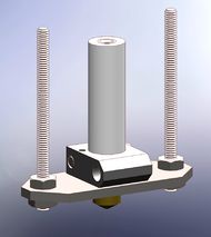
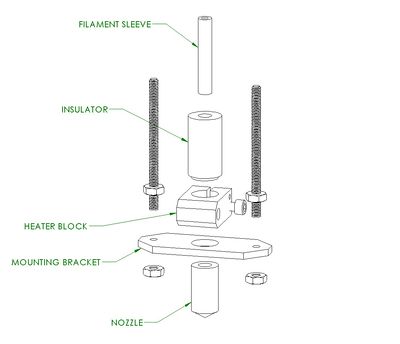
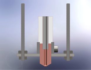
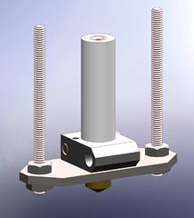
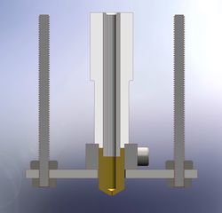
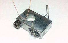
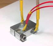
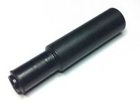
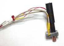
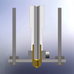
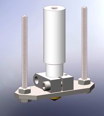
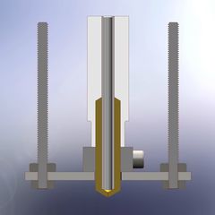
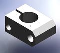
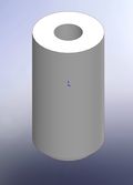
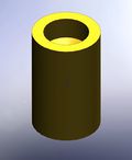
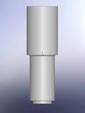
The assembly of the design so far consists of 5 main components: the heater block, the nozzle, the insulator, the filament sleeve and the mounting bracket. The heater block houses the resistor heating element and thermistor and also serves to clamp/hold the nozzle. The insulator thermally isolates the heater block from the extruder - it also keeps everything lined up. The mounting block holds everything securely against the extruder.
Stresses
The synthesis of this hot end focuses on the idea that common failure modes will not cause it to break itself. The intent is that everything is strong enough so that if the hot end completely jams - the extruder will just slip/strip on the filament. Rather than over-build the components, I put everything into compression so all the significant stresses are transmitted through the metal parts & the plastic can basically sit there and do nothing but insulate. This approach should also allow this hot end to survive all but the most extreme thermal runaway situation.
Heating
There is the possibility that by adding the additional part interface between the heater block and nozzle, that I'm going to reduce the overall thermal conductivity between the heater and nozzle. In an effort to counter this - I want to use good thermally conductive materials. Brass machines nicely and resists corrosion, but it's thermal conductivity is only ~115 W/m*K. Copper is one of the best thermal conductors at ~400 W/m*K and aluminum is not a half-bad alternative at ~180 W/m*K. By placing the thermistor and heaters on opposite sides of the heater block, combined with a securely clamped connection to the nozzle in the middle - I should get acceptable thermal transfer & temperature control (in theory..).
V 0.1
This is my first crude attempt at building a hot end. I was basing my design mostly off what I could see in other design notes and really had no idea how it would perform since this is literally my first hot end. I used 5/8" PEEK rod to build the insulator, 1/4" PTFE tubing, 1/2" copper rod for the nozzle, 1/2 x 3/4" aluminum bar for the heater block and 1/8 x 1" 303 stainless steel bar for the mounting plate.
I used a wirewound 6.8ohm, 3W axial resistor as the heating element.
This one to be specific:
http://search.digikey.com/us/en/products/W21-6R8JI/985-1102-1-ND/2401967
The wirewound aspect seems to be critical for high temperature survival (it's basically nichrome wire construction internally if I understand correctly), but I'm not sure what other aspects might be important beyond the power rating. I used the same thermistor as the J-head: B57560G104F 100kOhm EPCOS.
I used high temp Silicone RTV to glue the resistor and thermistor into the heater block and I used regular heatshrink to protect the wire leads. I used regular 18G braided wire to wire up the heater resistor and cat5 cable to wire the thermistor.
Drawings
|
|
|

|
| File:Nozzle v01.pdf | File:Heater v01.pdf | File:Insulator v01.pdf | File:Mount v01.pdf |
Specs
- Power: 21.2 Watts (as tested)
- Thermal mass: 12.8 J/K
Test Results
Thinking back now - I have no idea why I selected a higher value resistor than the JHead - I must have seen 6.8 ohms somewhere. Anyway - steady state the highest temperature I can achieve is 180C and it took an hour or so to get there. It's a little cold in my garage - around 50F - and I didn't do anything to insulate the heater block. ABS seems to extrude out of it ok, but I don't think this is hot enough to get good bonding of the extrusion.
The normal heatshrink and wire insulation actually seems to be holding up ok, but that could just be because I'm not yet into the correct temperature range of 220-230C. I'm not too worried about the heatshrink now, but on the next design I'll probably use wire with higher temperature insulation for at least the first few inches next to the heater block.
My EE partner in crime has quite correctly pointed out that the thermal mass of this design is also significantly more than the JHead and thus will result in slower reaction times - ie., worse PID heater control. To say the least - I think I can do better...
V 0.2
My first design revision - the V0.2 represents a significant step up the learning curve. This could/should probably be built with a single, lower value resistor like 3ohms, but since I have some of these 6.8's still laying around - I used two in parallel for more power output. This does put less stress on each resistor though. I also significantly reduced the thermal mass of the heated components - from 12.8 J/K in V0.1 to 5.7 J/K - now very similar to the J-Head Mk4. This means cheaper starting materials can also be used - 3/8" copper rod for the nozzle and 3/8 x 3/4" aluminum bar for the heater block. 1/2" PEEK rod could be used, but the current Wade Extruder design has a 5/8" pocket so it would need to be redesigned to accept a smaller rod or the top of the insulator will not self-center in the base of the extruder correctly.
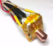
Assembly was similar to V0.1 except I added some glass fabric insulation around the heater block - held in place with kapton tape. This should significantly reduce heating losses to the air and steel mounting bracket. I also used some high temp wire for the wire leads for the first 6" on the resistors & thermistor - it seemed like a reasonable precaution.
1/16 x 1/2" fiberglass fabric: http://www.mcmaster.com/#catalog/118/3509/=gjquvm
18G 842F braided wire: http://www.mcmaster.com/#catalog/118/802/=gjqvbo
26G 400F flexible wire: http://www.mcmaster.com/#catalog/118/802/=gjqvks
Drawings
|

|
|

|
| File:Nozzle v02.pdf | File:Heater v02.pdf | File:Insulator v02.pdf | File:Mount v02.pdf |
Specs
- Power: 42.3 Watts (as tested)
- Thermal mass: 5.7 J/K
Test Results
The heater block on V0.2 definitely works far better than 0.1. Adding glass fabric secured with kapton tape also significantly helps insulate the block to both achieve operating temp quicker and maintain it easier. I didn't time it precisely, but I'd say it reached 230C in under 10 minutes.
In addition - the print head seems to work acceptably well. I get good quality prints and high-ish speeds are technically possible, although it results in excessive compressive stress on the filament and when the printer slows down at corners - the material continues to flow and bulges the corner details. http://www.youtube.com/watch?v=i5VEmBNV-Ww
At 15-20mm/s I get very nicely defined prints with good quality even on the 40mm tower test.

Unfortunately - I think 20-30mm/s is probably the upper limit for making quality prints and even at this speed - I have a significant leak of melted plastic escaping between the copper nozzle and the PEEK insulator. Over the course of about a half-hour, I'll get a penny-sized blob escaping - obviously this isn't going to work for longer prints.
V 0.3
There were only 2 goals for this revision - increase print speed & eliminate the leak. I thought the leak in V0.2 was caused because I machined the nozzle myself and the mill bit for the 1/4" hole wandered quite a bit in my lathe tail-stock. This widened the hole considerably and the PTFE liner was quite loose in the nozzle (although both had flat ends, so the ends matched ok). I decided instead to only drill the hole so that the PTFE would tightly fit in and left the PTFE end square because I had heard of problems where the PTFE wants to get drawn into the hole with a tapered end. I also increased the length in the nozzle that the PFTE engages, so that this would be a long, snug fit.
I also shortened the orifice length and "heat chamber" length. I wasn't sure what effect shorting the heater chamber length would be (the length inside the copper that's approx the same diameter as the filament) - but I thought shortening the orifice would reduce back-pressure and make it easier to extrude the liquid plastic. I hoped that shortening the length of engaged copper would also reduce friction and hoped it would achieve temperature quickly enough to melt appropriately.
Drawings

|

|
| File:Nozzle v03.pdf | File:Insulator v03.pdf |
Specs
- Power: 42.3 Watts (same heater as v0.2)
- Thermal mass: 6.3 J/K
Test Results
Suffice to say - let this version stand as a warning of what not to do. V0.3 was a conclusive failure. Not only did I not fix the leak - I made it 10x worse! Basically ALL of the melted ABS is extruded out the middle joint rather than the end...so much so, that it barely extrudes anything at all.
This isn't a total loss though - it tells me a lot about the dynamics at play and also motivated me to finally dig in and do some real thermodynamics & mechanical calculations. What I think I can intuitively take away from this failure is 2 more things - the ABS is easily melting completely inside the teflon, before it ever reaches the copper nozzle. So, I'm basically pumping liquid ABS into the joint. Also - the affect of the joint at the end of the teflon is MUCH more important than the fit of the hole its sitting in. By drilling the hole and leaving the end of the teflon square - I invited a much more substantial leak. And that leak tells me it's much easier for liquid ABS to escape along the side of over 5/8" of teflon tubing than it is to extrude out the end - so the backpressure from the contact with the copper must be considerable.
One interesting thing I hadn't thought about is how high the pressure of liquid ABS is inside the nozzle. If we assume our extruder is applying ~5lb of force - that's applying 456psi on a 3mm filament! At 10-15lb of force, we're talking 913-1370psi! That is a massive amount of pressure. Also - how much power is required to melt that extrusion? At 10mm/s of 0.4mm layer height x 0.72 width (1.8 WoTR) - we need about 1.2W to melt ABS or 0.3W for PLA. At 100mm/s - it's obviously 10x that, or about 12W/ABS & 3W/PLA. That's not insignificant, but at low speeds - it's quite small...so it sounds odd, but the hard part is not necessarily melting the plastic.
V 0.4
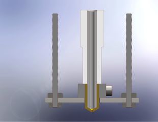
Version 0.4 shares the same goals as 0.3, but strives for a different result - no leak and faster prints. I am going out on a limb with this design - trying to leverage the disaster from 0.3 as an improvement. I hypothesize that keeping the filament in contact with as little copper as possible is going to be best. Since I'm concerned about the PTFE getting drawn into the smaller hole of the heat chamber in the nozzle - I'll just eliminate that hole! Instead, the teflon goes all the way to the end and tapers with the nozzle. Now there's not really anything to get drawn into and hopefully no leaks. This depends on the ABS heating almost completely inside the PTFE tube though - which would normally be a halfway decent insulator. Crazy? Yes. Crazy like a fox!
Due to the higher friction of PLA and its tendency to collapse & jam, this may only work for ABS, but that's ok for now...still learning & testing.
Drawings

|

|
| File:Nozzle v04.pdf | File:Insulator v04.pdf |
Specs
- Power: 42.3 Watts (same heater as v0.2)
- Thermal mass: 5.0 J/K
Test Results
Finally - a breakthrough! As I hypothesized, the full teflon lining cuts down very dramatically on backpressure & friction. Also - there's no problem at all melting enough extrusion even with limited contact on the copper nozzle. The nozzle flows so much easier, I have already had to cut the flow rate by 1/2 the feed rate and will probably have to reduce it even more. I quickly jumped to 30mm/s and this nozzle can easily keep up. I don't think 100mm/s or more will be a problem - likely other mechanical factors will start to weigh in more at that point - this should no longer play a limiting factor. Additional testing has yielded 40-50mm/s as the max feed for a 0.5mm nozzle at reasonable temperatures (~235C). The goal with V0.5 will be 100mm/s.
One other interesting side affect - when I just extrude material when not printing - I wait a couple seconds and pull the excess material away and it does not continue to ooze. This tells me there is extremely low stored compressive stress in the filament - it's really responding quickly.
Now - I just have to get my machine tuned to act appropriately with this fast-response hot end because although it doesn't "ooze" long after you stop printing - what does come out, comes out quickly! This combined with what is probably still excess print material is bulging the corners of my boxes as the print head slows down to turn. Still - this should be easily solved with print settings. Here's my first test print @ 30mm/s, 0.4mm layers & 0.5mm nozzle orifice:
https://www.youtube.com/watch?v=9W-QvdpS1FU
Also - ZERO leakage. I tapered the end of the teflon tube to match the 118 degree drill hole and left it about 1mm too long so that it would be slightly compressed as assembled (for good measure). I'm not sure if the extra compression is necessary, but after V0.3 I'm all paranoid. There doesn't seem to have been any ill affects seeing as it prints with ease and isn't leaking.
V 0.5
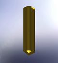
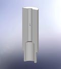
Version 0.5 attempts to further understand some of the fundamental mechanics by pushing all of the functional elements of V0.4 to the limit practically speaking - less ptfe insulation thickness and more heated length. Heated length increases from ~17mm to ~35mm. PTFE insulation thickness decreases from 1.59mm (1/16") to 0.794mm (1/32"). The hope is that this longer heated length and reduced insulation increases print speed and consistency, but at the very least it should provide some additional insight as to what works well, what doesn't and if/where there are limits to the construction.
Drawings
|
|
| File:Nozzle v05.pdf | File:Insulator v05.pdf |
Specs
- Power: 42.3 Watts (same heater as v0.2)
- Thermal mass: 8.9 J/K
- Time to reach 230C = 6.0 minutes
Test Results
At first when I tried printing I left the orifice length long (~0.070") thinking it would still flow easily since it would be so well heated/liquid. Well - it didn't - it didn't flow at all unless I put considerable force on the filament by hand. So - I redrilled with a much shorter orifice length - around 0.020" and accidentally redrilled the orifice diameter from 0.4mm to 0.6mm (stupid color coded drill bits). Those two factors combined dramatically reduced the backpressure though and resulted in a very free-flowing nozzle. Rather than build another nozzle, I did all my testing at 0.6mm orifice, but at some point I need to fabricate another narrower orifice nozzle and retest.
This hot end does ooze a bit more after extruding than V0.4, but not a lot. There seems to be a tradeoff on reduction of backpressure and ooze based on the length and size of the orifice. 0.020" might be a little short - 0.060" is probably too long - somewhere in the 0.025" to 0.035" seems pretty good depending on the diameter of the orifice.
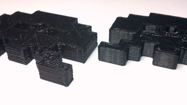
I spent a bit more time working on tuning the acceleration values in the firmware this time so that the deficiencies of my Prusa frame wouldn't detract from the quality of the print. Based on the fact I'm still reducing the flow to around 60% of the print speed, I think it's very likely this hot end could handle 100mm/s or more at 0.3mm layer height, but my frame is very nearly maxed at 75mm/s and I don't want to reduce the acceleration any more. I also added radius in Skeinforge to round out sharp corners to further reduce frame vibration and that helps quite a bit. The corner radius is still less than the frame shake and resulting print defects I was getting at 30mm/s and as you can see in this photo - the printer flow and resulting print quality is significantly improved even though the speed is more than doubled. One additional thing to note is that the V0.4 head was run at 235C and I'm running the V0.5 head at only 215C @ 75mm/s. At 50mm/s I can run the V0.5 head as low as 205C with ABS!
Here's video of the piece on the right being printed @ 75mm/s, 0.3mm layer height & 0.6mm orifice:
http://www.youtube.com/watch?v=VqeUsTeKMo8
At this point I'm fairly satisfied with the print quality and speed. Other factors are now limiting the performance and I need to work on improving the frame design so that I can push the hot end to higher speeds without increasing vibration, etc. V0.6 will probably be reserved for improving integration with the extruder and refining some of the assembly/construction.
