Wildseyed Simple Hot End
Release status: Working
| Description | Wildseyed Simple Hot End
|
| License | GPL
|
| Author | |
| Contributors | |
| Based-on | [[]]
|
| Categories | |
| CAD Models | |
| External Link |
Design Goals
When I began building my first RepRap, I found that many of you were experiencing problems with the hot ends, either because of design flaws, or the difficulty of manufacturing. I then convinced myself that there was plenty of room for improvement. I began with the following goals to guide me:
- Simple construction with readily available tools and materials
- Reliability
- Easy Maintenance
- Low Cost
Tools Required
- Drill Press
- Drill Bits
- Hack Saw
- Tap and Die Set
- Large Pliers or Vice Grips
- Flat File
- Calliper
- Scissors
- Soldering Iron
- Barrel Crimp Tool
- Small Brush or Cotton Swab
- Male Brass Coupling with threads to match Female coupling (For chucking the Female coupling in the drill press.)
Materials Required
- Aluminum Block - 1" x 1/2" x 1/2" (LxWxH)
- Brass Coupling - Air Hose Type Female 1/4"
- Copper MIG Type Welder Tip - 0.025/0.6mm
- Set Screws - M3x5mm(1), M3x10mm(4)
- PTFE Rod - 40mm x 1/2" (L x D)
- Thermistor - 100k, Glass Bead
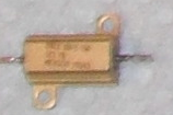
- Power Resistor - Aluminum Encased, Dale 5 Ohm 1% 5 Watt
- Kapton Tape
- Emergency Tape (degrades with use, so this is being deprecated in favor of more Kapton)
- Heat Sink Compound
- Crimp-on barrel connectors - Small
- Small Alligator clips
- Insulated Wire - Teflon preferred, but any will do
Assembly in Nine Easy Steps
- The Aluminum Block
- The Brass Coupling
- The MIG Welder Tip
- The PTFE Rod
- The Thermistor
- The Power Resistor
- The Wraps
- The Mounting
- The Connections
Step One - The Aluminum Block
Using a punch, and a 5/16" bit, drill a hole through all, from the top of the aluminum block. The hole should be equi-distant from the three nearest edges. For example, if the block's top dimensions are 1" x 1/2", the the hole should be centred at 1/4" x 1/4". Next, widen the top half of the 5/16" hole using a 7/16" bit. Finally, use a M3 bit to drill a hole for the set screw. Tap threads into it.
Note: When drilling the aluminum block on a drill press, holding the block using pliers will help eliminate troublesome vibrations.
Step Two - The Brass Coupling
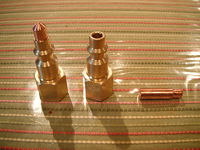
Drill down through the small end with a 7/32" bit to widen the opening. Drill down again, but only half way, using a 1/4" bit. This will allow the MIG welder tip to slip onto the coupling freely, but still provide grip when press fit later.
Step Three - The MIG Welder Tip
Drill the inside of the MIG welder tip to 3.5mm per http://www.youtube.com/watch?v=Whyoa2U5lvY
When the small opening of the coupling has been widened, insert the MIG welder tip into the coupling, and place it on a hard, smooth surface, or anvil.
Making sure that the MIG tip and coupling are aligned, use a smooth-faced hammer to tap the MIG tip into the coupling. It should only take three or four strikes to accomplish this step. Observe that the MIG tip hole gets smaller with each hit. Resist the urge to make really tiny holes. This will usually result in a clogged tip.
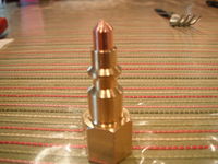
Once the MIG tip is attached, mount the male coupling in the drill press, and screw the female brass coupling onto it. Using the flat file and drill press, grind away the MIG tip at 45 degrees, until the taper produces a fine tip with a small flat surrounding the extrusion hole.
Step Four - The PTFE Rod
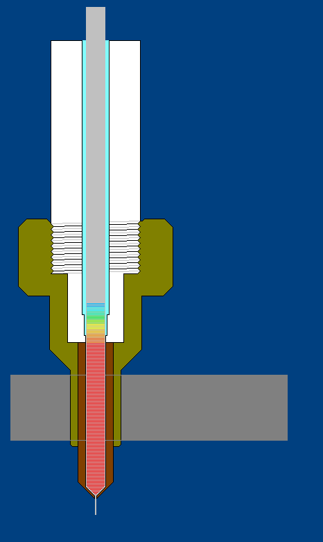
Cut the rod to length (40mm - 45mm). Insert into the drill press and drill a 3mm hole through all. While still attached to the drill press. Next, take a slightly larger bore, and drill through all but the last 1mm, leaving a small lip at the end. Finally, drill the rod out again with a bore of 4mm. This eliminates a great deal of heat transfer to the filament before it reaches the melt pot.
(The image at http://thingiverse-production.s3.amazonaws.com/renders/d2/22/6b/ef/c4/WildseyedHotEndComponents_display_medium.jpg and the cross section below seem to indicate turning a step on the outer surface of the PTFE rod. One might want to do this after working the inside to preserve concentricity.)
Step Five - The Thermistor
The thermistor is the most likely cause of failure in any hot end. It is very fragile, and subject to shorts if not installed properly. Careful installation will ensure reliable operation, and accurate temperature measurements.
For this step, you will need a 100k Thermistor, and several lengths of Kapton tape. The goal is to encase the thermistor in several layers of Kapton tape, to ensure that the leads are insulated and supported, while still exposing as much of the glass bead as possible to direct contact with the heated surface.
On the underside of the aluminum block, place the glass bead of the thermistor against the copper nozzle, making sure that no part of the wires are exposed to bare metal. Hold it in this position, and move on to the next step, where we will attach the power resistor.
Step Six - The Power Resistor
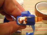
Apply a small amount of heat sink compound to the bottom of the power resistor case, and place the resistor against the aluminum block, with the connector ends facing out to either side. While holding the resistor and thermistor in place, begin wrapping the assembly in Kapton (preferred) or silicone tape (also known as rescue tape, and emergency tape). Emergency tape eventually degrades, F.Y.I.
Step Seven - The Wrap
To begin wrapping the block, you begin by cutting a 6 inch piece of the tape into three strips, lengthwise. The narrow strip is easier to handle, and fits well into the nooks.
For the first strip, press the end of the tape against the top of the power resistor, and make at least two complete turns around the block. Allow the connector ends to protrude. Continue wrapping, alternate from side to side. Keep this first layer on the end of the block, so that it covers the edges and corners.
On the second and subsequent turns of the first strip, capture the thermistor, making sure no part of the copper leeds in tape touches any metal edge or corner that has not been yet covered.
The second strip should cover the glass bead, and be wound around both sides of the nozzle.
The third strip should bind the perimeter.
<videoflash>Ngfl6JRcPpo</videoflash>
Step Eight - The Mounting
This hot end has been tested on the standard Wade's Extruder and the Greg's Accessible Wade's. Mounting requires the use of four M3.5 holes, two drilled from either side of the extruder body, into the corners of the 1/2 mounting hole located on the bottom of the extruder body. The standard Wades usually has a bigger hole than the PTFE, but this should not present a problem. The extruder is held clamped in this hole using four M4x8mm set screws.
Proper alignment requires that a piece of filament be placed through the extruder body, and into the PTFE tube while the set screws are being tightened evenly 1/2 turn at a time. Once the PTFE tube is secure, check the filament. It should move freely, or with very little force. If it binds hard at all, insert a 3mm drill bit and turn by hand to remove excess material from the tube. Be sure to remove all material, or you will clog the tip.
Step Nine - The Connections
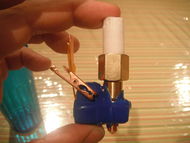
Connection of the power resistor uses two small copper alligator clips, attached and soldered to a 24 inch set of leads. Likewise, the thermistor is crimped to lengths of wire using small barrel connectors. Insulate these with shrink tubing. (pictures coming)
Using It
From http://forums.reprap.org/read.php?70,147404,147824#msg-147824 :
My design copes just fine. If the PTFE is shaped properly, it will never slip out of the brass coupling. Since the couplings vary by region, it's best to keep a caliper on hand and measure the inner diameters and depth before shaping the rod. At the transition from small to large, I put a slight taper to help slip the threads over the rod. Also make sure the small end bottoms out on the MIG tip, or you won't get a good seal there.
The one thing to avoid is leaving the hot end at operating temperature without printing. This is the case for most designs. Eventually, the temperature inside the PTFE could get hot enough to soften the filament, and cause a jam.
Separation from the extruder body is a possibility if too much pressure is exerted by the stepper. This is remedied by using a nozzle opening no smaller than 0.5mm, and setting the stepper driver current such that it allows the motor to stall, rather than push at any cost.
On a Wade's or Greg's body, the PTFE rod should be clamped in tightly using four M3-8mm Set Screws. If it pinches the hole a little, it alright. Just run a 3mm bit in and out a couple of times.
I print with ABS only, but I do keep the temperature at 230C. This seems to give the best long term results.
I actually have the versions of this hot end, but I have not had the time lately to put up new instructions. If you want to get more info, and some pictures, drop me a line on my gmail wildseyed@...
