part slightly too big
Posted by awmt102
|
part slightly too big July 10, 2011 01:42PM |
Registered: 13 years ago Posts: 43 |
Hi all,
I have been tuning my Skeinforge settings for a few days now and am fairly happy with the look of the calibration parts so decided to try out an actual RepRap part that I have a spare of for comparison (attached file).
Its a fairly simple part that clamps a board onto the 8mm studding. My part came out looking pretty good but when I offered it up to the studding it does not quite fit. On closer inspection the part seems to be marginally larger than the spare I have. Initially I thought that my steps/mm might be slightly off but then I realised that if that were the case the part would fit the studding with no problem.
It is almost as if my part has an extra shell around it making the footprint bigger and the channel down the middle tighter.
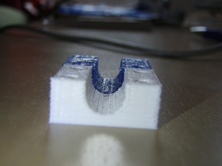
Can anybody suggest what might be wrong? I have attached the stl file I am using and two photos of the correctly sized part (white) and my printed part (blue). I realise my holes are the wrong size - I need to play with the stretch plugin but did not want it enabled whilst trying to sort out this problem.
My Skeinforge setup is as follows (only the settings I think are relevant, let me know if there are others that might be helpful):
Bottom:
Additional height 0.0
Altitude 0.2
Carve
Layer thickness 0.3
Perimeter width ratio 1.0
Clip
Clip over perimter width 0.4
Max connection 10.0
Dimension
Relative Extrusion
Retraction speed 13.0
Retraction distance 2.5
Restart 0.1
Export
Do not change output
Fill
Diaphragm Period 100
Diaphragm thickness 0
Extra Shells on LAternating solid layers 2
Extra shells on base 1
Extra shells on sparse 1
Grid circle separation 0.05
Grid extra overlap 0.1
Grid junction separation band 10
Grid junction separation over octagon radius at end 0.0
Grid junction separation over octagon radius at middle 0.0
Infil Begin Rotation 45
Infill Begin repeat 1
infill odd layer 90
Infill Pattern Line
infill perimeter overlap 0.2
infil solidity 0.6
infil width over thickness 1.3
Solid surface thickness 3
Multiply
Centre X 100
Centre Y 100
Skirt
Gap 15
Layers to index 1
Speed
Feed rate 60
Flow rate 60
Orbital feed rate 0.5
Perimeter feed rate 0.7
Perimeter flow rate 0.7
Temperature
all 200
All other plugins disabled.
Happy to provide more detail if neccessary.
Thanks in advance.
Andy
I have been tuning my Skeinforge settings for a few days now and am fairly happy with the look of the calibration parts so decided to try out an actual RepRap part that I have a spare of for comparison (attached file).
Its a fairly simple part that clamps a board onto the 8mm studding. My part came out looking pretty good but when I offered it up to the studding it does not quite fit. On closer inspection the part seems to be marginally larger than the spare I have. Initially I thought that my steps/mm might be slightly off but then I realised that if that were the case the part would fit the studding with no problem.
It is almost as if my part has an extra shell around it making the footprint bigger and the channel down the middle tighter.
Can anybody suggest what might be wrong? I have attached the stl file I am using and two photos of the correctly sized part (white) and my printed part (blue). I realise my holes are the wrong size - I need to play with the stretch plugin but did not want it enabled whilst trying to sort out this problem.
My Skeinforge setup is as follows (only the settings I think are relevant, let me know if there are others that might be helpful):
Bottom:
Additional height 0.0
Altitude 0.2
Carve
Layer thickness 0.3
Perimeter width ratio 1.0
Clip
Clip over perimter width 0.4
Max connection 10.0
Dimension
Relative Extrusion
Retraction speed 13.0
Retraction distance 2.5
Restart 0.1
Export
Do not change output
Fill
Diaphragm Period 100
Diaphragm thickness 0
Extra Shells on LAternating solid layers 2
Extra shells on base 1
Extra shells on sparse 1
Grid circle separation 0.05
Grid extra overlap 0.1
Grid junction separation band 10
Grid junction separation over octagon radius at end 0.0
Grid junction separation over octagon radius at middle 0.0
Infil Begin Rotation 45
Infill Begin repeat 1
infill odd layer 90
Infill Pattern Line
infill perimeter overlap 0.2
infil solidity 0.6
infil width over thickness 1.3
Solid surface thickness 3
Multiply
Centre X 100
Centre Y 100
Skirt
Gap 15
Layers to index 1
Speed
Feed rate 60
Flow rate 60
Orbital feed rate 0.5
Perimeter feed rate 0.7
Perimeter flow rate 0.7
Temperature
all 200
All other plugins disabled.
Happy to provide more detail if neccessary.
Thanks in advance.
Andy
|
Re: part slightly too big July 10, 2011 02:47PM |
Registered: 13 years ago Posts: 1,611 |
|
Re: part slightly too big July 11, 2011 06:37AM |
Registered: 13 years ago Posts: 43 |
The official part is the correct size. It is definately correct and mine wrong as the official one fits over the 8mm studding that it is designed for and mine does not.
The issue is definately that each outside edge of the object is a little larger than it should be, I just do not know why my Skeinforge settings are causing this.
Thanks
Andy
The issue is definately that each outside edge of the object is a little larger than it should be, I just do not know why my Skeinforge settings are causing this.
Thanks
Andy
|
Re: part slightly too big July 11, 2011 08:53AM |
Registered: 13 years ago Posts: 1,611 |
I think your Perimeter width ratio setting under carve is wrong. With it set to 1, you are saying that it is extruding a perfect 0.3mm diameter filament. In fact, each layer gets squashed onto the previous layer and spreads out. This may be why your part as fractionally bigger in the X and Y dimensions. By setting it to, for example, 1.5, the path of the nozzle will be inset, and the filament squashing pushes out to where the edge of the part should be, rather tracing the edge of the part with the nozzle and squashing beyond the edge. Hope that makes sense!
There are lots of other threads on the forum about PWOT (Perimeter width over thickness), including some about how to work it out mathematically. For 3mm filament and a 0.5mm nozzle, which extrudes a 0.7mm diameter filament (measured using digital calipers), printing a 0.4mm layer means my PWOT ratio is 1.8. See nophead's blog for the maths! [hydraraptor.blogspot.com]
Also, your infill is set to 0.6 (or 60%) which may make the part very 'full'. Infill solidity can be turned down to 20 to 25% (0.2 to 0.25) without compromising part strength.
|
Re: part slightly too big July 11, 2011 09:07AM |
Registered: 14 years ago Posts: 3,742 |
For calibrating always set the infill to 1.0!
If you are using an infill of 0.2 or 0.25 and are pushing too much plastic you won't necessary know it because there is empty room for it to disappear into. With 1.0 (100%) fill you KNOW if there is too much (or too little plastic) being pushed.
Bob Morrison
Wörth am Rhein, Germany
"Luke, use the source!"
BLOG - PHOTOS - Thingiverse
|
Re: part slightly too big July 11, 2011 10:05AM |
Registered: 13 years ago Posts: 1,611 |
Not necessarily Bob, as it also depends on the INFILL width over thickness; if it is set incorrectly, say to 1 when it should be 1.5, a 60% infill will look like 100%, but it doesn't necessarily mean you are pushing too much filament, just that the infill paths will be spaced too close together, as the WOT ratio governs the spacing of the path the nozzle takes. Getting the width over thickness settings correct seems vital to me, and can be calculated by measuring the diameter of filament extruded from the hotend before worrying about whether you are extruding too much or too little. That's why the only numbers that matter to Skeinforge in the Carve tab are layer thickness and Perimeter Width over thickness, and we now (generally) set Feed rate and flow rate the same. Skeinforge can work out everything else, but it relies on your calibration of X, Y, Z and extruder steps/mm being accurate. It's why you don't need to tell SK what nozzle size you have.
Edited 1 time(s). Last edit at 07/11/2011 10:06AM by droftarts.
Edited 1 time(s). Last edit at 07/11/2011 10:06AM by droftarts.
Sorry, only registered users may post in this forum.