Tripteron Implementation
Posted by Apsu
|
Re: Tripteron Implementation November 25, 2016 10:18AM |
Registered: 8 years ago Posts: 5,232 |
|
Re: Tripteron Implementation November 25, 2016 10:27AM |
Registered: 7 years ago Posts: 143 |
Quote
o_lampe
With a little longer extrusion, you could win a bit print room,too.
The MGN12 rails are sold in fixed length, but 2020 extrusion sells tailored to your needs. See blue circles in the attached pic.
Yep, you are indeed correct. I had a bunch of 305mm extrusion and 300mm rails, so I just went with what I had, but absolutely I could expand the frame so the rails don't run the full length and up the % of build to frame volume by pushing the singularities out past the rail-sized build cube.
Edited 1 time(s). Last edit at 11/25/2016 10:27AM by Apsu.
|
Re: Tripteron Implementation November 25, 2016 01:00PM |
Registered: 7 years ago Posts: 143 |
Well Christmas came early, my E3D extruder and hotend are here, got a 200x300mm boro glass bed, and the extruder motor will be arriving later today. Looks like I might actually be printing tonight with any luck.
Just need to design a groovemount that can attach to my effector and we're basically there. Maybe bed-mounting clips if I'm feeling really enterprising, but I have a differential IR Z probe, so I can probably just set the bed on something mostly flat and probe to level it.
Exciting!
Just need to design a groovemount that can attach to my effector and we're basically there. Maybe bed-mounting clips if I'm feeling really enterprising, but I have a differential IR Z probe, so I can probably just set the bed on something mostly flat and probe to level it.
Exciting!
|
Re: Tripteron Implementation November 26, 2016 01:21AM |
Registered: 7 years ago Posts: 143 |
SHE PRINTS!!
YouTube Link

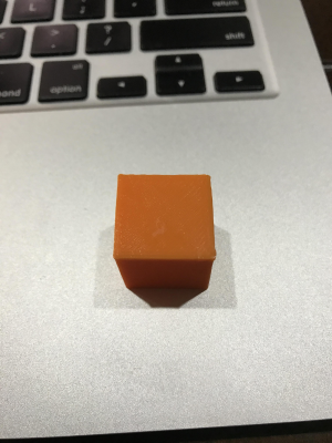
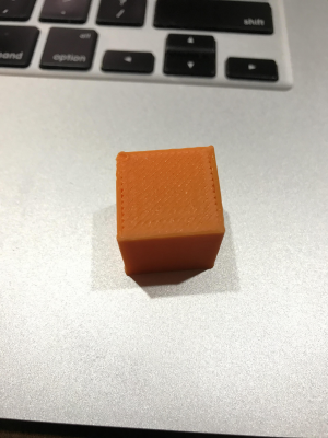
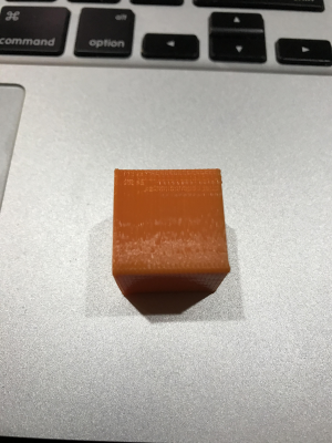
Plenty left to work on, but I got the rest of the bits necessary to mount everything and got it printing successfully.
Here's the result:
Bottom
Top
Side
I forgot to add some smarter ending gcode and it squatted on the corner on top a bit, and I was testing different accelerations along the way...
But all of that is improvable, the fundamental behavior works! Mission accomplished
YouTube Link

Plenty left to work on, but I got the rest of the bits necessary to mount everything and got it printing successfully.
Here's the result:
Bottom
Top
Side
I forgot to add some smarter ending gcode and it squatted on the corner on top a bit, and I was testing different accelerations along the way...
But all of that is improvable, the fundamental behavior works! Mission accomplished

|
Re: Tripteron Implementation November 26, 2016 03:27AM |
Registered: 9 years ago Posts: 32 |
|
Re: Tripteron Implementation November 26, 2016 07:16AM |
Registered: 8 years ago Posts: 5,232 |
|
Re: Tripteron Implementation November 26, 2016 02:22PM |
Registered: 7 years ago Posts: 143 |
Quote
o_lampe
Good job, Sir!
I've seen worse test cubes.
In the side view I see some regular wobble every 5-6 layers. Makes me wonder if the z-stepper would need a gearbox or just a lead screw drive?
..now back to watching this video again
Oh there's all kinds of stuff wrong here, haha. The Z axis is absolutely jumping a little due to being belted and having 200 micron resolution. It also slips when the motor turns off, because non-counterweighted belted Z is terrible
 I plan to put a leadscrew on it ASAP. I might even try ballscrews, maybe even on every axis. We'll see!
In addition, Z needs some bracing in a serious way. The tower bends a little under higher accel and other forces, and it tilts everything and causes bounce. But that's not as difficult to deal with, just need to decide how exactly I want to brace it and put it together.
|
Re: Tripteron Implementation November 27, 2016 11:22PM |
Registered: 7 years ago Posts: 143 |
Alrighty, time for an update.
Overall, this was a huge success, I'd say. Managed to build something that makes reasonable prints and can be improved further. It also seems to be the first machine of its kind ever actually built, so that's pretty cool too
There are some challenges left to solve with the orthogonal Tripteron which are particularly difficult, and I think I'm going to pivot slightly (pun intended) to one of the other two Tripteron configurations. Specifically the colinear one, as seen on the 9th page of this paper, Figure 4(b) on the right.
It struck me immediately that it is essentially a linear delta in layout, if you flip it upside down. I made some CAD mockups and did some motion studies (here and here), and I'm really interested in the properties of this approach.
Some of the positives I see:
There's more that I like, but that's a good elevator pitch for now.
I completed the IK math and wrote some simple python to test it here, but I will also explain the math here, to hopefully make it very clear. It's actually quite simple!
Our goal is to provide a vector describing a movement of the effector and calculate the required motion of each of the three actuators, alpha/beta/gamma.
First we define a constant, which is based on the angle the arms are to the actuators. The relationship is in fact a simple tangent, and doesn't change. We can use 30 degrees as an example.
t = tan(30)
Then we compute the actuator tower rotation constants. These are coefficients that will scale the actuation on each tower for the effector xyz motion, with respect to that tower's orientation. Note that we do not need a 3D matrix or to shift the origin or to know where the towers are located. None of that matters because we're not driving the arm angles or lengths, it's only the Z rotation of the tower that determines the actuator scaling. We will consider the alpha tower to have no rotation.
alpha_x = sin(0)
alpha_y = cos(0)
beta_x = sin(120)
beta_y = cos(120)
gamma_x = sin(240)
gamma_y = cos(240)
Next we do the actual calculation for each component of the movement vector. This is essentially a 2D rotation matrix broken out a little bit. Note that z is not scaled because z movement is 1:1 on all actuators, moving up or down together.
alpha = x*alpha_x*t - y*alpha_y*t + z
beta = x*beta_x*t - y*beta_y*t + z
gamma = x*gamma_x*t - y*gamma_y*t + z
And that's it. No exponents, square roots, division, no trig-per-move. Just some pre-computed constants and 6 muls/3 adds per move (if we optimize by including *t in the rotation constants). It's way easier than the IK for a delta, and also pretty much any other FDM mechanics I've seen, except of course pure Cartesian. There's also some easy simplifications we can make, for example: sin(0) = 0, so alpha_x = 0, and cos(0) = 1, so alpha_y = 1, thus alpha = -y*t + z.
I'm more than willing to answer questions and would love to hear your feedback, even if you think the orthogonal Tripteron is better than sliced bread and you hate the shape of deltas
For now, I'm going to pursue the colinear configuration because I find it even more appealing and potentially easier to engineer, with some additional benefits, so I'll be designing some brackets and new test arms, and reusing the parts from my first prototype to put it together.
Stay tuned!
Edited 2 time(s). Last edit at 11/28/2016 05:48PM by Apsu.
Overall, this was a huge success, I'd say. Managed to build something that makes reasonable prints and can be improved further. It also seems to be the first machine of its kind ever actually built, so that's pretty cool too

There are some challenges left to solve with the orthogonal Tripteron which are particularly difficult, and I think I'm going to pivot slightly (pun intended) to one of the other two Tripteron configurations. Specifically the colinear one, as seen on the 9th page of this paper, Figure 4(b) on the right.
It struck me immediately that it is essentially a linear delta in layout, if you flip it upside down. I made some CAD mockups and did some motion studies (here and here), and I'm really interested in the properties of this approach.
Some of the positives I see:
- All actuator motion is linear, still. There are mechanical reduction factors (increasing resolution) that must be multiplied to scale the motion, but they're constant and the inverse kinematics are very straightforward.
- Being linear, full accuracy is present everywhere in the build volume
- All three arms are symmetric, and suspend the platform from above, meaning the gravity load is shared and it's very likely I can use much lighter arms/joints than the orthogonal configuration. In that one, the Z arm receives an imbalanced load that's not easy to solve with these materials.
- Arms never impinge on the build volume no matter what you do!
- Since the actuators are not orthogonal, the effector axes are coupled in IK, but are still parallel mechanically. This is true of all the Tripterons, so this isn't "worse" somehow
- Being so close to a linear delta in construction, it's quite possible you could convert many delta kits to a Tripteron and improve their behavior at minimal cost
- The angle between the actuators and the arm joint plane is something that can be tweaked as part of the engineering considerations. Larger angles give more resolution at the cost of less max Z height (actuators move up/down more for a given X/Y motion), while smaller give less resolution but gain Z height. The angle also effects what kinds of loads the arms/joints experience, so this is going to be the primary area of focus for an initial prototype. That means lots of room to hack and tweak based on material choice and arm design.
- It looks really unique, and I really like the symmetry. I like deltas for similar reasons, but I also like their frame construction. You get lots of Z height and a good XY volume:frame ratio on a delta, and this machine is no different. I'm seeing 90% and up at least in terms of build:frame volume.
There's more that I like, but that's a good elevator pitch for now.
I completed the IK math and wrote some simple python to test it here, but I will also explain the math here, to hopefully make it very clear. It's actually quite simple!
Our goal is to provide a vector describing a movement of the effector and calculate the required motion of each of the three actuators, alpha/beta/gamma.
First we define a constant, which is based on the angle the arms are to the actuators. The relationship is in fact a simple tangent, and doesn't change. We can use 30 degrees as an example.
t = tan(30)
Then we compute the actuator tower rotation constants. These are coefficients that will scale the actuation on each tower for the effector xyz motion, with respect to that tower's orientation. Note that we do not need a 3D matrix or to shift the origin or to know where the towers are located. None of that matters because we're not driving the arm angles or lengths, it's only the Z rotation of the tower that determines the actuator scaling. We will consider the alpha tower to have no rotation.
alpha_x = sin(0)
alpha_y = cos(0)
beta_x = sin(120)
beta_y = cos(120)
gamma_x = sin(240)
gamma_y = cos(240)
Next we do the actual calculation for each component of the movement vector. This is essentially a 2D rotation matrix broken out a little bit. Note that z is not scaled because z movement is 1:1 on all actuators, moving up or down together.
alpha = x*alpha_x*t - y*alpha_y*t + z
beta = x*beta_x*t - y*beta_y*t + z
gamma = x*gamma_x*t - y*gamma_y*t + z
And that's it. No exponents, square roots, division, no trig-per-move. Just some pre-computed constants and 6 muls/3 adds per move (if we optimize by including *t in the rotation constants). It's way easier than the IK for a delta, and also pretty much any other FDM mechanics I've seen, except of course pure Cartesian. There's also some easy simplifications we can make, for example: sin(0) = 0, so alpha_x = 0, and cos(0) = 1, so alpha_y = 1, thus alpha = -y*t + z.
I'm more than willing to answer questions and would love to hear your feedback, even if you think the orthogonal Tripteron is better than sliced bread and you hate the shape of deltas

For now, I'm going to pursue the colinear configuration because I find it even more appealing and potentially easier to engineer, with some additional benefits, so I'll be designing some brackets and new test arms, and reusing the parts from my first prototype to put it together.
Stay tuned!
Edited 2 time(s). Last edit at 11/28/2016 05:48PM by Apsu.
|
Re: Tripteron Implementation November 28, 2016 10:29AM |
Registered: 7 years ago Posts: 7 |
|
Re: Tripteron Implementation November 28, 2016 11:03AM |
Registered: 7 years ago Posts: 143 |
Quote
kayrangandhi
From the experience with bearing joints, do you think making a planar joint with a bearing joint+ a linear rail would be a good idea?
I'm not 100% sure what you mean by planar joint or bearing joint + linear rail. I've got linear rails already, to which the shoulder bearing joints will attach. Do you mean a compliant laminar joint by "planar joint"?
|
Re: Tripteron Implementation November 28, 2016 11:40AM |
Registered: 11 years ago Posts: 5,780 |
It would be interesting to see what a dial gauge clamped to the extruder carriage reads when you move it around the bed surface.
Ultra MegaMax Dominator 3D printer: [drmrehorst.blogspot.com]
Ultra MegaMax Dominator 3D printer: [drmrehorst.blogspot.com]
|
Re: Tripteron Implementation November 28, 2016 12:14PM |
Registered: 7 years ago Posts: 143 |
|
Re: Tripteron Implementation November 28, 2016 12:36PM |
Registered: 11 years ago Posts: 5,780 |
I don't know if the sag in the arms would be linear and correctable by just tilting the print bed. It seems like the motion might define a pretty complex, unflat surface.
Edited 1 time(s). Last edit at 11/28/2016 12:37PM by the_digital_dentist.
Ultra MegaMax Dominator 3D printer: [drmrehorst.blogspot.com]
Edited 1 time(s). Last edit at 11/28/2016 12:37PM by the_digital_dentist.
Ultra MegaMax Dominator 3D printer: [drmrehorst.blogspot.com]
|
Re: Tripteron Implementation November 28, 2016 12:49PM |
Registered: 7 years ago Posts: 143 |
Quote
the_digital_dentist
I don't know if the sag in the arms would be linear and correctable by just tilting the print bed. It seems like the motion might define a pretty complex, unflat surface.
(assuming your talking about the delta-like configuration) Well given the offset angles of the arm joint plane, it would depend on what's sagging and where, I suppose. Of course the goal is to mechanically ensure the deflection is as minimal as possible, by maximizing rigidity and minimizing weight.
We'll see what I can come up with
|
Re: Tripteron Implementation November 28, 2016 01:33PM |
Registered: 7 years ago Posts: 7 |
Quote
Apsu
Quote
kayrangandhi
From the experience with bearing joints, do you think making a planar joint with a bearing joint+ a linear rail would be a good idea?
I'm not 100% sure what you mean by planar joint or bearing joint + linear rail. I've got linear rails already, to which the shoulder bearing joints will attach. Do you mean a compliant laminar joint by "planar joint"?
Something like this
|
Re: Tripteron Implementation November 28, 2016 04:05PM |
Registered: 7 years ago Posts: 143 |
Quote
kayrangandhi
Quote
Apsu
Quote
kayrangandhi
From the experience with bearing joints, do you think making a planar joint with a bearing joint+ a linear rail would be a good idea?
I'm not 100% sure what you mean by planar joint or bearing joint + linear rail. I've got linear rails already, to which the shoulder bearing joints will attach. Do you mean a compliant laminar joint by "planar joint"?
Something like this
Ah, gotcha. I misread you at first. I'm not sure why you'd want that necessarily, certainly not for this application. You'd need a motor on the shoulder joint to drive the second rail in relation to the carriage, and that would significantly weight the whole assembly. Not to mention the rails are hardened and made of steel, so they're not remotely lightweight

|
Re: Tripteron Implementation November 29, 2016 09:19PM |
Registered: 7 years ago Posts: 143 |
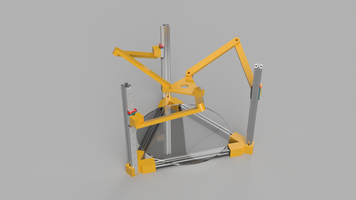
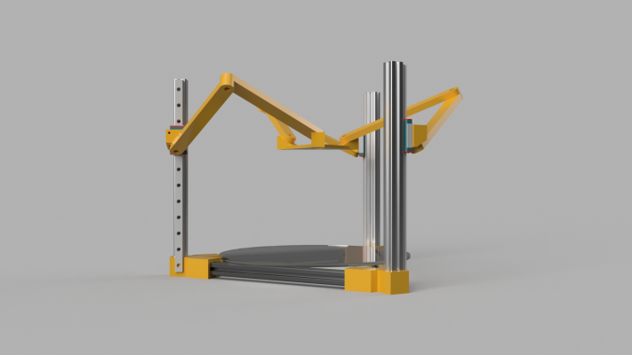
Little more proper renderings of a mockup. And yes, I'm aware the rails are overlapping the corner brackets ;P
I completed the forward kinematics as well, and have some code written up for Smoothieware that I will test after I build the prototype, and after testing, submit for inclusion upstream.
The code is here, and the comments there describe the method I'm using to define the forward/inverse kinematic equations. The code itself is just a little simplified and optimized.
|
Re: Tripteron Implementation November 29, 2016 10:23PM |
Registered: 7 years ago Posts: 7 |
Quote
Apsu
Quote
kayrangandhi
Quote
Apsu
Quote
kayrangandhi
From the experience with bearing joints, do you think making a planar joint with a bearing joint+ a linear rail would be a good idea?
I'm not 100% sure what you mean by planar joint or bearing joint + linear rail. I've got linear rails already, to which the shoulder bearing joints will attach. Do you mean a compliant laminar joint by "planar joint"?
Something like this
Ah, gotcha. I misread you at first. I'm not sure why you'd want that necessarily, certainly not for this application. You'd need a motor on the shoulder joint to drive the second rail in relation to the carriage, and that would significantly weight the whole assembly. Not to mention the rails are hardened and made of steel, so they're not remotely lightweight
What i meant with that draft assembly was to try another way to assemble one of the arms of the tripteron, using the same effector, but looking for more arm rigidity and less joint play/backlash. Of course the full design would have one assembly like that per tower.
Correct me if I'm wrong, but I understand each arm defines a tilted circle that slides along the vertical tower and the effector location is defined by the intersection of the 3 tilted circles right? So having a linear rail free to slide and whose carriage turns over a bearing could be another way to define a circular workspace the same as two segments with a bearing. One advantage would be having screw holes for fixing the bearing.
Anyway, keep up this very interesting work. Besides the advantages you cited, the weight applied on the arms can help with backlash acting as a pre-load. And the IK is quite elegant and 8-bit friendly, do you have hints on how to use it on Marlin?
I'm currently designing/building a Kossel with magnetic joints and I'm seriously considering designing compatible MGN12 carriages and effector with some 608s I have laying around.
|
Re: Tripteron Implementation November 30, 2016 12:52AM |
Registered: 7 years ago Posts: 143 |
Quote
kayrangandhi
What i meant with that draft assembly was to try another way to assemble one of the arms of the tripteron, using the same effector, but looking for more arm rigidity and less joint play/backlash. Of course the full design would have one assembly like that per tower.
Correct me if I'm wrong, but I understand each arm defines a tilted circle that slides along the vertical tower and the effector location is defined by the intersection of the 3 tilted circles right? So having a linear rail free to slide and whose carriage turns over a bearing could be another way to define a circular workspace the same as two segments with a bearing. One advantage would be having screw holes for fixing the bearing.
Yes, indeed, that is how it works. I understand what you were getting at now, I'd have to model it up to see how it behaves in motion and at extremities. Interesting idea though.
Quote
Anyway, keep up this very interesting work. Besides the advantages you cited, the weight applied on the arms can help with backlash acting as a pre-load. And the IK is quite elegant and 8-bit friendly, do you have hints on how to use it on Marlin?
I'm afraid I haven't done a ton of hacking on Marlin, but I would assume that you could find how they handle linear deltas and just replace the math with this math, if it's not particularly easy to simply add another kinematic system alongside cartesian and delta.
Quote
I'm currently designing/building a Kossel with magnetic joints and I'm seriously considering designing compatible MGN12 carriages and effector with some 608s I have laying around.
Hey, by all means, if you think you see a way for it to work, go for it. After all, stubbornly pursuing the mechanics is how I got so far. I'd be curious to see your results!
|
Re: Tripteron Implementation November 30, 2016 01:20AM |
Registered: 7 years ago Posts: 143 |
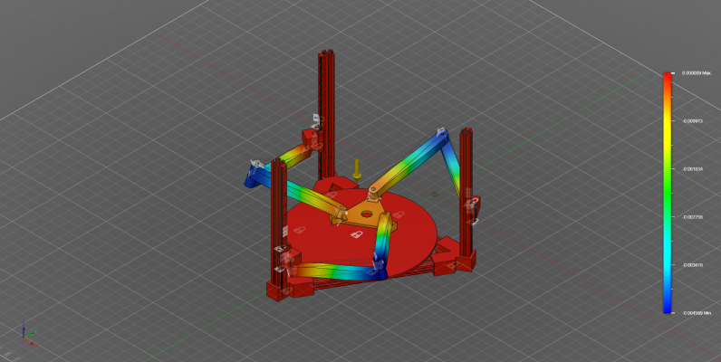
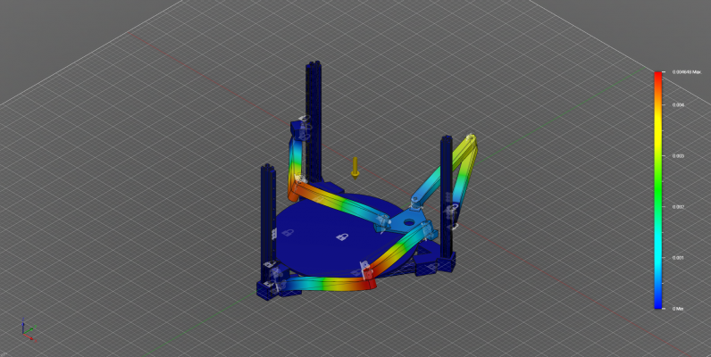
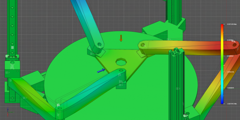
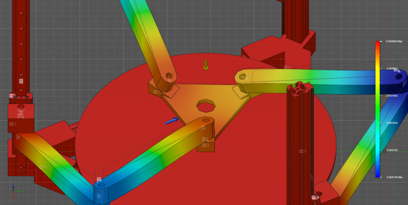
Small update
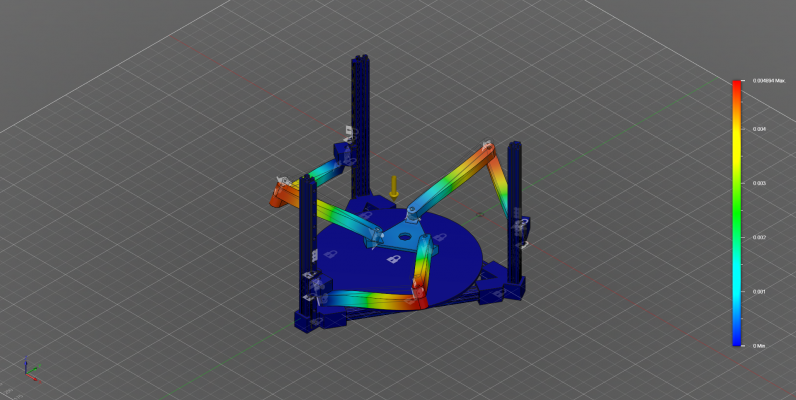
Trying out 20mm x 20mm arms with square cross-sections and hollow inside with 2mm shells, simulating just gravity to see balanced joint stresses. I chose 25deg arm angles to maximize the loads. Keep in mind if you've never seen something like this, the *huge* visual deformations are because the software amplifies small values so they're visible and you can see what's happening easier. The legend on the right indicates actual values, in mm.
Total deformation is 0.0049mm max, but the effector is barely moved. Down in the 0.0001mm range.
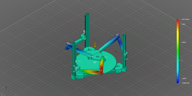
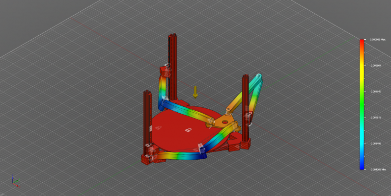
Then X/Y/Z
Z is the most interesting, because just gravity is pulling the effector down in the 0.000001mm or below range. Really the effector's deflection is non-existent within the error of the steppers/belts/etc.
The arm deflections are interesting for the purpose of cross-section/material/joint design/etc, but the *most* useful thing about them is in contrast to the effector. Many orders-of-magnitude larger deflections in the arms and joints, at least in the symmetric central position, do not result in effector motion, because the forces are well-balanced by the constraint mechanics.
I intend to run more sims on different positions and with loads due to acceleration/hotend weight/etc, but for now I'm satisfied that this is incredibly reasonable with very light, simple arms, and can be further engineered to achieve high speed/accels from there
Edited 1 time(s). Last edit at 11/30/2016 01:24AM by Apsu.
Trying out 20mm x 20mm arms with square cross-sections and hollow inside with 2mm shells, simulating just gravity to see balanced joint stresses. I chose 25deg arm angles to maximize the loads. Keep in mind if you've never seen something like this, the *huge* visual deformations are because the software amplifies small values so they're visible and you can see what's happening easier. The legend on the right indicates actual values, in mm.
Total deformation is 0.0049mm max, but the effector is barely moved. Down in the 0.0001mm range.
Then X/Y/Z
Z is the most interesting, because just gravity is pulling the effector down in the 0.000001mm or below range. Really the effector's deflection is non-existent within the error of the steppers/belts/etc.
The arm deflections are interesting for the purpose of cross-section/material/joint design/etc, but the *most* useful thing about them is in contrast to the effector. Many orders-of-magnitude larger deflections in the arms and joints, at least in the symmetric central position, do not result in effector motion, because the forces are well-balanced by the constraint mechanics.
I intend to run more sims on different positions and with loads due to acceleration/hotend weight/etc, but for now I'm satisfied that this is incredibly reasonable with very light, simple arms, and can be further engineered to achieve high speed/accels from there

Edited 1 time(s). Last edit at 11/30/2016 01:24AM by Apsu.
|
Re: Tripteron Implementation November 30, 2016 04:50AM |
Registered: 8 years ago Posts: 5,232 |
I don't want to rain on your parade, but I don't see huge advantages against a common delta or the cartesian tripteron?
OK, you win headroom against a delta, but the elbows sticking out everywhere weights more against it.
Have you done the same simulation ( hollow 2020 arms ) with the last tripteron? Is there a significant difference?
I'd spend more time in improving the cartesian tripteron.
Especially one sentence of the tripteron paper regarding this delta worries me:
They said it is over constrained and they consider using ball joints on the effector.
To me that sounds like you have to build it with no tolerance in alignment to make it work without binding..
Sorry if I sound a bit negative, I just had a 24h print fail in the middle of a print...
Edited 1 time(s). Last edit at 11/30/2016 04:52AM by o_lampe.
OK, you win headroom against a delta, but the elbows sticking out everywhere weights more against it.
Have you done the same simulation ( hollow 2020 arms ) with the last tripteron? Is there a significant difference?
I'd spend more time in improving the cartesian tripteron.
Especially one sentence of the tripteron paper regarding this delta worries me:
They said it is over constrained and they consider using ball joints on the effector.
To me that sounds like you have to build it with no tolerance in alignment to make it work without binding..
Sorry if I sound a bit negative, I just had a 24h print fail in the middle of a print...

Edited 1 time(s). Last edit at 11/30/2016 04:52AM by o_lampe.
|
Re: Tripteron Implementation November 30, 2016 07:58AM |
Registered: 8 years ago Posts: 312 |
I love how in the square version, you can print on any surface. You can place it on any flat surface and print something.
With good calibration, you could print an object straight onto the roof of a car, for instance. Mount it with sucker feet, calibrate and print a new air scoop. Magic!
I need to start experimenting with one. Man you do good work!
Lykle
With good calibration, you could print an object straight onto the roof of a car, for instance. Mount it with sucker feet, calibrate and print a new air scoop. Magic!
I need to start experimenting with one. Man you do good work!
Lykle
|
Re: Tripteron Implementation November 30, 2016 10:28AM |
Registered: 7 years ago Posts: 143 |
Quote
o_lampe
I don't want to rain on your parade, but I don't see huge advantages against a common delta or the cartesian tripteron?
OK, you win headroom against a delta, but the elbows sticking out everywhere weights more against it.
I see several advantages. For one, symmetric arm assemblies suspending the platform from above with no possibility of the arms impinging on the build volume is a definite advantage over the orthogonal Tripteron.
And, being linear, the advantage over a linear delta is constant accuracy, since it's also not driving the angles of a triangle for actuation.
Quote
Have you done the same simulation ( hollow 2020 arms ) with the last tripteron? Is there a significant difference?
I'd spend more time in improving the cartesian tripteron.
I did tons of simulation and spent weeks printing arms -- some of which I posted here, but there was a lot more. The asymmetry and motor decoupling actually introduces more challenges than the coupled/colinear version.
Quote
Especially one sentence of the tripteron paper regarding this delta worries me:
They said it is over constrained and they consider using ball joints on the effector.
You misread the paper. They say that *all* Tripteron configurations are overconstrained, and talk about how that's never been an issue for them in their other robotics work. They then proceed to talk about choosing to build the "original overconstrained" configuration for their prototype -- which is the orthogonal robot. The universal joint discussion was simply to point out that you could introduce another DOF that ends up being passive to further constrain it, and discuss the pros and cons. Not that they are suggesting you do so.
Quote
To me that sounds like you have to build it with no tolerance in alignment to make it work without binding..
Sorry if I sound a bit negative, I just had a 24h print fail in the middle of a print...
Sorry to hear about your print, that sucks.
As for tolerances and alignment and binding... yes. Engineering all this is a real challenge. But it's certainly doable

|
Re: Tripteron Implementation November 30, 2016 12:58PM |
Registered: 7 years ago Posts: 143 |
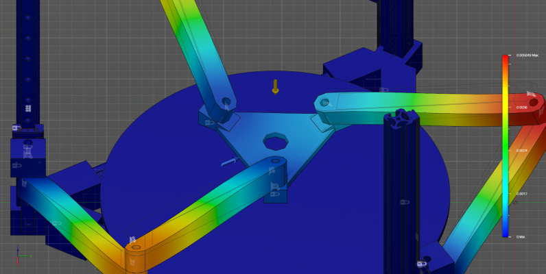
Did some offset platform simulations to compare, and looks like the behavior is the same with respect to effector deflection 
Total displacement
Z displacement
Looks like the isostatic behavior is excellent. Looking good!

Total displacement
Z displacement
Looks like the isostatic behavior is excellent. Looking good!
|
Re: Tripteron Implementation November 30, 2016 04:41PM |
Registered: 7 years ago Posts: 143 |
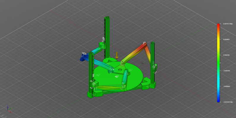
And last check for good measure. Added a 1N lateral load to the effector, which is *ENORMOUS* acceleration for how much these parts weigh (effector is 50g as-modeled). This is equivalent to 20,000mm/s^2 acceleration (F=ma, 1N = 0.05kg * 20m/s^2, 20m/s^2 = 20000mm/s^2).
Total:
XY:
Z:
The last one is particularly interesting, because the effector deforms more than with gravity, as expected, but even under such a heavy load it does not deform much at all in Z, still well below the resolution of the machine. Also seeing nearly 0 deformation in X/Y is very reassuring.
Total:
XY:
Z:
The last one is particularly interesting, because the effector deforms more than with gravity, as expected, but even under such a heavy load it does not deform much at all in Z, still well below the resolution of the machine. Also seeing nearly 0 deformation in X/Y is very reassuring.
|
Re: Tripteron Implementation November 30, 2016 05:17PM |
Registered: 7 years ago Posts: 7 |
|
Re: Tripteron Implementation November 30, 2016 05:29PM |
Registered: 7 years ago Posts: 143 |
Quote
kayrangandhi
I don't see why you couldn't do that with the Delta version
Not sure what you mean. This is the delta-like version. Did you mean why can't I simulate the orthogonal version -- the one I built and got printing? Because I did simulate it, I didn't post quite as much of the simulations but I simulated the hell out of a ton of arm designs.

The difference is in the orthogonal version each arm is helped by the constraints (due to orientation) of the others, but not all other DOFs are constrained by each other arm. Just one of the two cartesian DOFs. Meaning that the loads aren't shared in the same way that this orientation is.
In this colinear version, each arm takes part of the load of each other arm, seemingly regardless of the direction of the load. That's why I'm sharing the simulations, because I know for myself at least, I didn't have a clear physical intuition about how well it would work or exactly how it would distribute just from looking at it.
Edited 1 time(s). Last edit at 11/30/2016 05:31PM by Apsu.
|
Re: Tripteron Implementation November 30, 2016 05:40PM |
Registered: 7 years ago Posts: 7 |
Quote
Lykle
I love how in the square version, you can print on any surface. You can place it on any flat surface and print something.
With good calibration, you could print an object straight onto the roof of a car, for instance. Mount it with sucker feet, calibrate and print a new air scoop. Magic!
I need to start experimenting with one. Man you do good work!
Lykle
I don't see why you couldn't do that (print on any surface) with the Delta version.
Sorry, I should've quoted correctly ,what software do you use for cad and simulation?
|
Re: Tripteron Implementation November 30, 2016 05:49PM |
Registered: 7 years ago Posts: 143 |
|
Re: Tripteron Implementation December 01, 2016 12:13AM |
Registered: 7 years ago Posts: 143 |
Decided to try the outer arm links jointed on top of the inner, to lift them away from the build volume a bit more
YouTube Link
Gifv link for endless fun
Sorry for the low quality, free license of Fusion doesn't let me render prebaked motion studies at higher res ;P
YouTube Link
Gifv link for endless fun
Sorry for the low quality, free license of Fusion doesn't let me render prebaked motion studies at higher res ;P
Sorry, only registered users may post in this forum.
