Intro, AnyCubic Kossel Plus Calibration?
Posted by nutz
|
Intro, AnyCubic Kossel Plus Calibration? September 13, 2017 04:43AM |
Registered: 8 years ago Posts: 7 |
Hello,
I appologize regarding length.
Intro
I've been following 3D printing for years. It is such a kewl idea and it works too, it's nut just sci-fi.
Frankly I cotton to the delta theme, these robots are so sexy. )
)
But in any case, after expending many days on the web, I convinced myself that I could
make a delta from scratch and inexpensively too. In retrospect, I should have just bought a
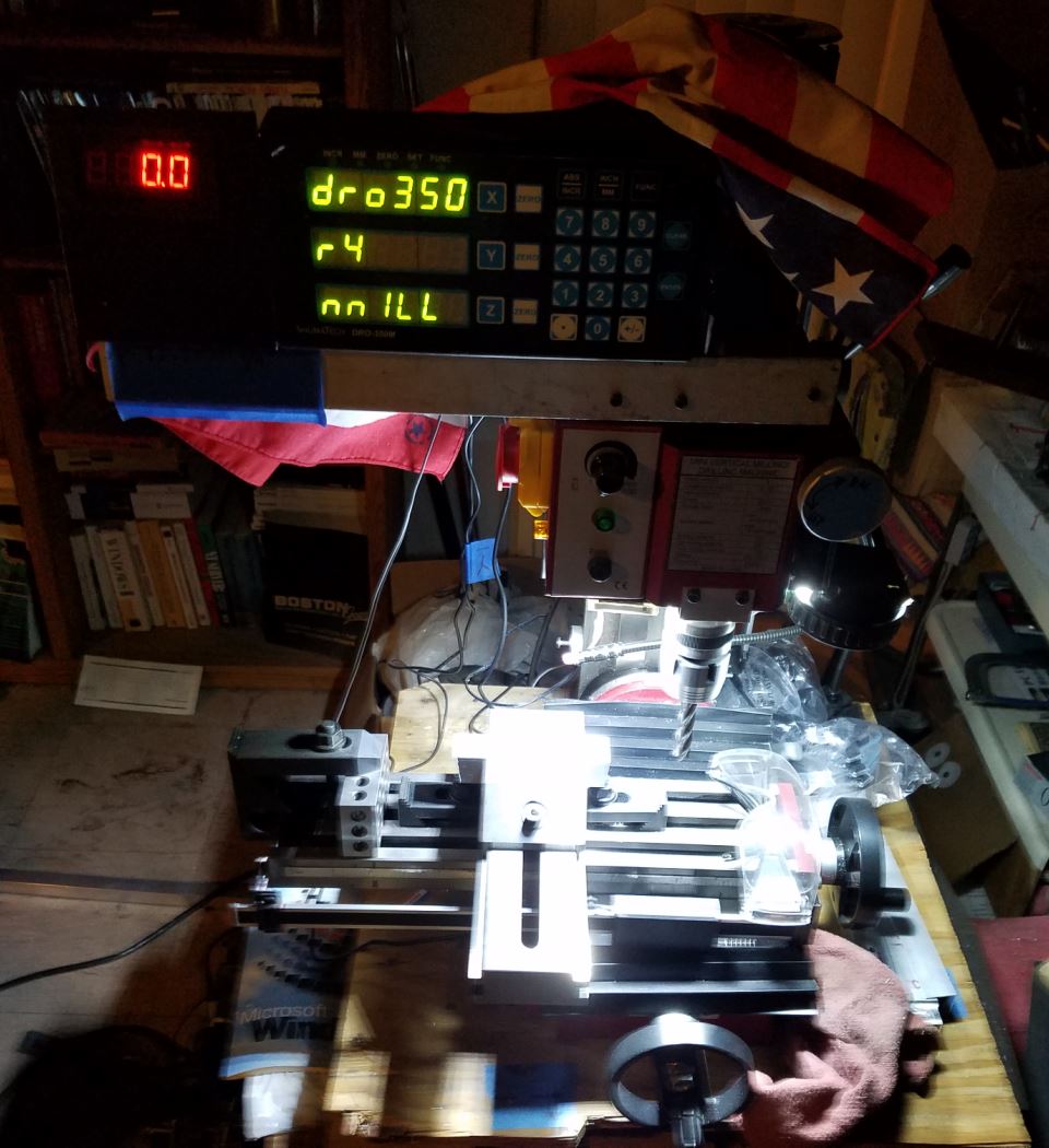
kit, but I learned a bunch things, and milling (using my X2 mini-mill and then later modifying it,
by scratching together a retro-reflective IR spindle RPM tachometer, and then further
modding by adding iGaging 'DRO' scales/LCD readouts (really helped, but not good enough)
and then upgrading by acquiring an old-stock, but new WildHorse Innov/SchumaTech
(OpenHW) DRO-350 DRO, etc. And lots of support accessories, --dial-indicators, end-mills,
holders, screwless vice, etc. see the photo of the X2, the red 7-seg is the tach readout, the
two screw/bracket over the spindle holds the IR retro-reflector sensor. In any case, it is the
journey to the goal that's the fun.
I finally came to the realization that my mini-mill just can't hold the tolerances required and I
gave up fabbing an all metal delta from scratch. So, amidst a great big pile of aluminum swarf, smooth
rods, custom stepper motor mounts, RAMPs boards, I finally saw a delta in the price and capability
range that my sensibilities could embrace. I bought an 'AnyCubic Kossel Plus, linear-guide delta printer kit',
for around $250 U$ + Free Shipping.
I have to say, it was quite fun constructing the kit and it went fairly smoothly, although I thought about
measuring the various components with metric rulers & calipers, but was lazy. There were a few instances,
where I more-or-less was forced to guess about things, although the provided fabrication manual is
reasonably useful, considering that its of (inexpensive) Chinese origin. A few of the photos in the
manual are so dark pertinent details are lost. The end-stop cables are a bit too short, a mere 100mm
or so additional length would have been appropriate and the extruder stepper-motor cable is much too long,
while one of the tower stepper cables are too short. I cut a section out of the extruder cable and
lengthened the other (with a bit'o smok'n solder), rendering both of those cables the same length
which rememdied that problem.
However, the calibration of the AC Kossel-Plus has been anything but fun. Maybe its because
I am becoming an old part, but at this juncture I have no idea what is happening or what need
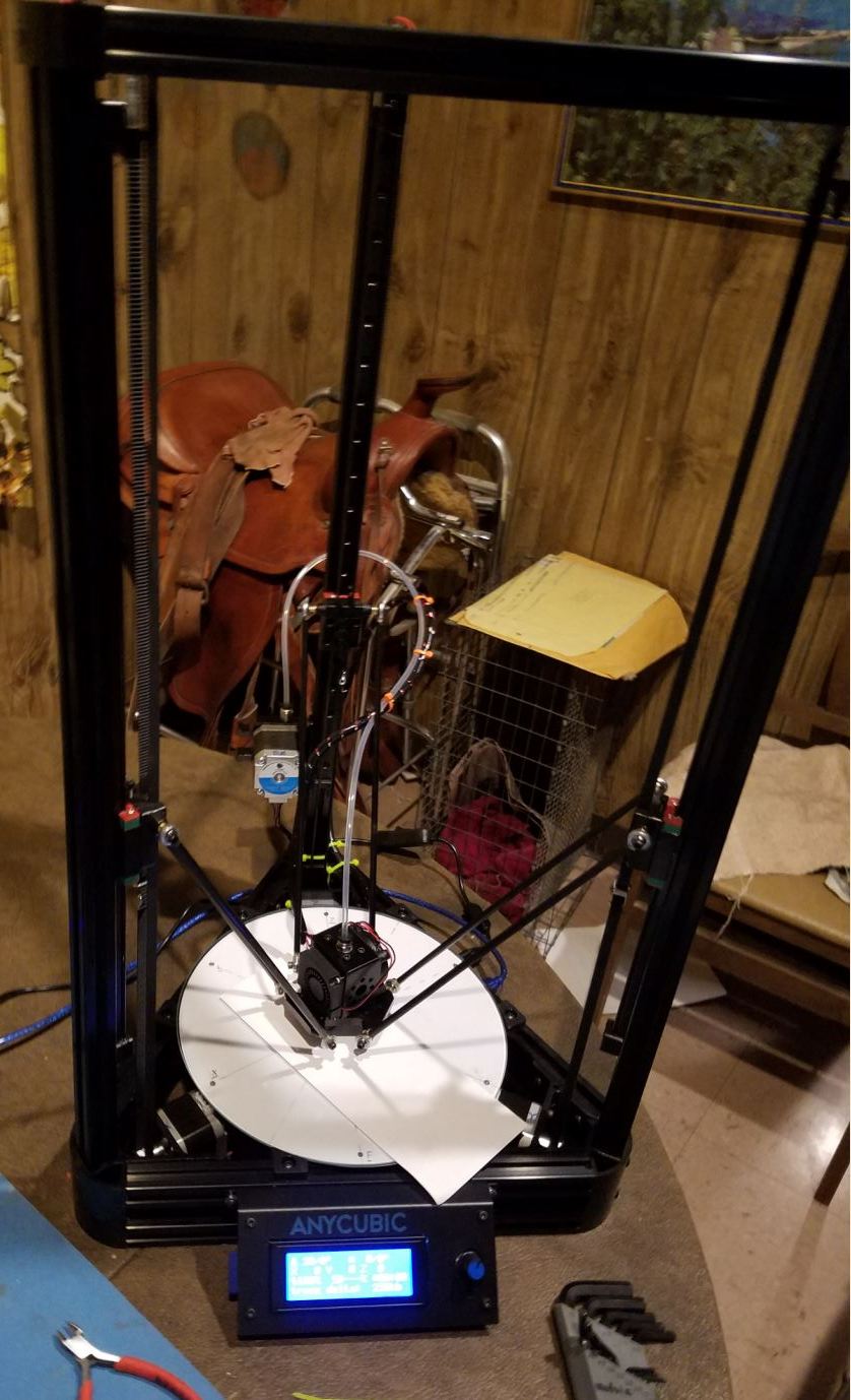
be done to get this neato machine printing properly? See the two photos of the AC Kossel Plus.
The vendor implied that they 'pre-calibrated' the Marlin FW, up to a certain extent, considering
that the printer is a hobbyiest fabricated mechanical kit, and as such, there would likely be
mechanical variations which could throw-off 'factory calibrations'. However, I expected those
variations to be somewhat minor. But there seems to be something significantly amiss, whether
it be my understanding, and-or, the fidelity of my fabrication skill to match intended completed
structure dynamics, or possibly worse case, the printer is just not properly or well designed?
However I tend not to believe the latter. The vendor's calibration info is practically non-existent.
The provided youtube tutorials are either out of order or are incomplete, they certainly do not
depict resolution tutorials, which is what I require.
AC Kossel Plus Cal Info & Problems
So here's the deal, I downloaded the AC (AnyCubic) Kossel zip file containing Marlin v1.1.0-RC8
Arduino (ATmega2560) firmware source, PronterFace/PronSol/PrintRun, Slic3r, Cura, etc files. I
installed everything, along with the USB driver and I got the Marlin FW to compile
(my first Arduino experience), which quite frankly was the simplest compile I have ever seen.
But then the problems started.
First problem, I could not cause the printer USB to connect to the PC
(HP Pavilion EliteBook 8735W 17" LapTop, Win7 Pro) via PronterFace, yet the Arduino IDE
successfully uploads the image via USB to the 'TriGorilla' ATmega chip? I discovered
after much fiddling around that there is some form of an initialization problem? In my 'eco-system',
PronterFace **NEVER** connects without first loading the Arduino IDE, whether
or not a compile/upload is has been instantiated. The next step, after the IDE load
is invoking PronterFace, which locks-up the printer, and then immediately exit PronterFace
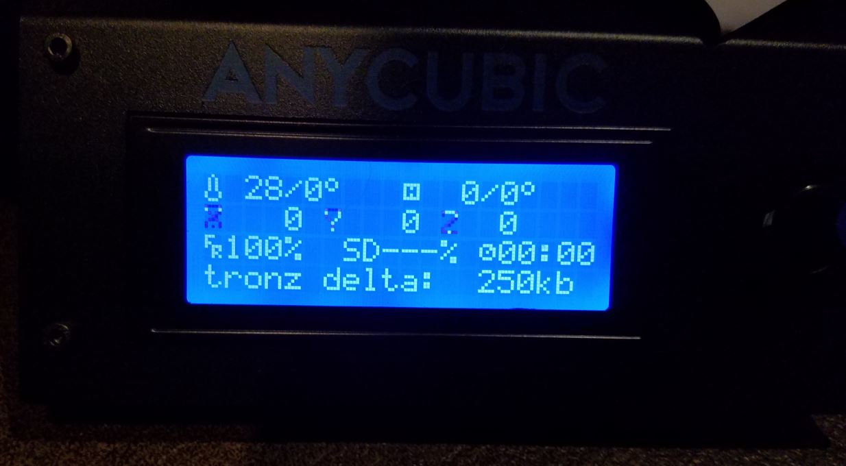
without doing anything; wait about 15 seconds, while observing the 4x20 LCD on the printer,
after which, apparently, the Marlin/ATmega2560 resets itself (watch-dog?), displaying
the boot splash. After that, I re-invoke PronterFace, and then it can connect?
Something really screwy going on there. Its a workaround, however kludgie it might be.
Then after fiddling around using the AC kit manual cal info and watching their YouTube tutorials
(which are somewhat lacking for dummies), nothing is working correctly. When I have a
problem, I desire step-by-step instruction, sans any guessing.
I hand crafted a calibration circle on paper, dotting the center and points near the position
of the towers, recessed 10mm from the edge, centered on equidistant 60° epoch lines around
the circumference. I mounted the calibration 'disc' under the glass for a visual calibration
reference.
The claimed build area for the Kossel Plus is 230mm dia, glass extends to 240mm.
I was finally able to calibrate the effector nozzle to center height. I got that dialed in, I think? As
when I (via PronSol), I invoke: G1 X0 Y0 F7000 Z0,
the effector zips down to the center of the glass bed surface, barely grabbing paper.
In (Marlin) configuration.h, I changed the setting from the factory 300mm to:
#define MANUAL_Z_HOME_POS = 295.26 // barely grabs paper
However, when I move to do the tower height adjustments everything is wayout, and the
adjustment is outside the endstop micro-switch adjustment range. The mechanical
endstops are affixed to the top of the linear-rail, which prevents downward adjustment, without
moving the entire rail on each of the towers.
Here are the readings for bed-zeroing:
While the:
X-Tower: G1 X-115 Y-58 Z15.78 - barely grabs paper, on X epoch out at the 230mm circle
Y-Tower: G1 X115 Y-63 Z16.65 - barely grabs paper, on Y epoch out at the 230mm circle
Z-Tower: G1 X7 Y145 Z21.32 - barely grabs paper, on Z epoch out at the 230mm circle
As one can see from the Z readings, the printer bed is a 'bowl' low in the middle and high on
the sides, and the effector isn't any where near the tower positions.
So after reading various folks posting around the 'Net, I started looking at the radius setting, and
the FW was configured for a different printer model than for the "Kossel Plus" I bought, as the
source was set for 180mm /2, whereas the 'Plus' model is 230mm /2. So, I suspect that
there are bunches of config.h configurations that do not match my 'Plus' model requirements.
But I do not know enough to know what I should do to remedy the matter. As AnyCubic implement
Marlin, one would expect that they would include in their "Technical Specs" the details
of the pertinent calibration items, such as the:
DELTA_SMOOTH_ROD_OFFSET,
DELTA_EFFECTOR_OFFSET, etc,
but they don't.
Then there's the matter of something being saved into EEprom, as I when change things,
but I don't see any affect? I've been considering getting out my JTAGICE MkII to zero
the EEprom, just to get things back to index, so-to-speak. But I don't desire to screw things up
worse, by flopping around like a chicken with its head cut-off. I need help.
I have read lots of stuff, and reviewed numerous calibration processes, but frankly I
am quite confused at this juncture, and I feel fairly certain that some in this community
has a much better understanding of this than I, and very likely can offer useful thoughtful
direction.
I very much appreciate any help (or criticizm) that might be offered.
Thanks,
nutz
09-13-2017
I appologize regarding length.
Intro
I've been following 3D printing for years. It is such a kewl idea and it works too, it's nut just sci-fi.
Frankly I cotton to the delta theme, these robots are so sexy.
)But in any case, after expending many days on the web, I convinced myself that I could
make a delta from scratch and inexpensively too. In retrospect, I should have just bought a
kit, but I learned a bunch things, and milling (using my X2 mini-mill and then later modifying it,
by scratching together a retro-reflective IR spindle RPM tachometer, and then further
modding by adding iGaging 'DRO' scales/LCD readouts (really helped, but not good enough)
and then upgrading by acquiring an old-stock, but new WildHorse Innov/SchumaTech
(OpenHW) DRO-350 DRO, etc. And lots of support accessories, --dial-indicators, end-mills,
holders, screwless vice, etc. see the photo of the X2, the red 7-seg is the tach readout, the
two screw/bracket over the spindle holds the IR retro-reflector sensor. In any case, it is the
journey to the goal that's the fun.
I finally came to the realization that my mini-mill just can't hold the tolerances required and I
gave up fabbing an all metal delta from scratch. So, amidst a great big pile of aluminum swarf, smooth
rods, custom stepper motor mounts, RAMPs boards, I finally saw a delta in the price and capability
range that my sensibilities could embrace. I bought an 'AnyCubic Kossel Plus, linear-guide delta printer kit',
for around $250 U$ + Free Shipping.
I have to say, it was quite fun constructing the kit and it went fairly smoothly, although I thought about
measuring the various components with metric rulers & calipers, but was lazy. There were a few instances,
where I more-or-less was forced to guess about things, although the provided fabrication manual is
reasonably useful, considering that its of (inexpensive) Chinese origin. A few of the photos in the
manual are so dark pertinent details are lost. The end-stop cables are a bit too short, a mere 100mm
or so additional length would have been appropriate and the extruder stepper-motor cable is much too long,
while one of the tower stepper cables are too short. I cut a section out of the extruder cable and
lengthened the other (with a bit'o smok'n solder), rendering both of those cables the same length
which rememdied that problem.
However, the calibration of the AC Kossel-Plus has been anything but fun. Maybe its because
I am becoming an old part, but at this juncture I have no idea what is happening or what need
be done to get this neato machine printing properly? See the two photos of the AC Kossel Plus.
The vendor implied that they 'pre-calibrated' the Marlin FW, up to a certain extent, considering
that the printer is a hobbyiest fabricated mechanical kit, and as such, there would likely be
mechanical variations which could throw-off 'factory calibrations'. However, I expected those
variations to be somewhat minor. But there seems to be something significantly amiss, whether
it be my understanding, and-or, the fidelity of my fabrication skill to match intended completed
structure dynamics, or possibly worse case, the printer is just not properly or well designed?
However I tend not to believe the latter. The vendor's calibration info is practically non-existent.
The provided youtube tutorials are either out of order or are incomplete, they certainly do not
depict resolution tutorials, which is what I require.
AC Kossel Plus Cal Info & Problems
So here's the deal, I downloaded the AC (AnyCubic) Kossel zip file containing Marlin v1.1.0-RC8
Arduino (ATmega2560) firmware source, PronterFace/PronSol/PrintRun, Slic3r, Cura, etc files. I
installed everything, along with the USB driver and I got the Marlin FW to compile
(my first Arduino experience), which quite frankly was the simplest compile I have ever seen.
But then the problems started.
First problem, I could not cause the printer USB to connect to the PC
(HP Pavilion EliteBook 8735W 17" LapTop, Win7 Pro) via PronterFace, yet the Arduino IDE
successfully uploads the image via USB to the 'TriGorilla' ATmega chip? I discovered
after much fiddling around that there is some form of an initialization problem? In my 'eco-system',
PronterFace **NEVER** connects without first loading the Arduino IDE, whether
or not a compile/upload is has been instantiated. The next step, after the IDE load
is invoking PronterFace, which locks-up the printer, and then immediately exit PronterFace
without doing anything; wait about 15 seconds, while observing the 4x20 LCD on the printer,
after which, apparently, the Marlin/ATmega2560 resets itself (watch-dog?), displaying
the boot splash. After that, I re-invoke PronterFace, and then it can connect?
Something really screwy going on there. Its a workaround, however kludgie it might be.
Then after fiddling around using the AC kit manual cal info and watching their YouTube tutorials
(which are somewhat lacking for dummies), nothing is working correctly. When I have a
problem, I desire step-by-step instruction, sans any guessing.
I hand crafted a calibration circle on paper, dotting the center and points near the position
of the towers, recessed 10mm from the edge, centered on equidistant 60° epoch lines around
the circumference. I mounted the calibration 'disc' under the glass for a visual calibration
reference.
The claimed build area for the Kossel Plus is 230mm dia, glass extends to 240mm.
I was finally able to calibrate the effector nozzle to center height. I got that dialed in, I think? As
when I (via PronSol), I invoke: G1 X0 Y0 F7000 Z0,
the effector zips down to the center of the glass bed surface, barely grabbing paper.
In (Marlin) configuration.h, I changed the setting from the factory 300mm to:
#define MANUAL_Z_HOME_POS = 295.26 // barely grabs paper
However, when I move to do the tower height adjustments everything is wayout, and the
adjustment is outside the endstop micro-switch adjustment range. The mechanical
endstops are affixed to the top of the linear-rail, which prevents downward adjustment, without
moving the entire rail on each of the towers.
Here are the readings for bed-zeroing:
While the:
X-Tower: G1 X-115 Y-58 Z15.78 - barely grabs paper, on X epoch out at the 230mm circle
Y-Tower: G1 X115 Y-63 Z16.65 - barely grabs paper, on Y epoch out at the 230mm circle
Z-Tower: G1 X7 Y145 Z21.32 - barely grabs paper, on Z epoch out at the 230mm circle
As one can see from the Z readings, the printer bed is a 'bowl' low in the middle and high on
the sides, and the effector isn't any where near the tower positions.
So after reading various folks posting around the 'Net, I started looking at the radius setting, and
the FW was configured for a different printer model than for the "Kossel Plus" I bought, as the
source was set for 180mm /2, whereas the 'Plus' model is 230mm /2. So, I suspect that
there are bunches of config.h configurations that do not match my 'Plus' model requirements.
But I do not know enough to know what I should do to remedy the matter. As AnyCubic implement
Marlin, one would expect that they would include in their "Technical Specs" the details
of the pertinent calibration items, such as the:
DELTA_SMOOTH_ROD_OFFSET,
DELTA_EFFECTOR_OFFSET, etc,
but they don't.
Then there's the matter of something being saved into EEprom, as I when change things,
but I don't see any affect? I've been considering getting out my JTAGICE MkII to zero
the EEprom, just to get things back to index, so-to-speak. But I don't desire to screw things up
worse, by flopping around like a chicken with its head cut-off. I need help.
I have read lots of stuff, and reviewed numerous calibration processes, but frankly I
am quite confused at this juncture, and I feel fairly certain that some in this community
has a much better understanding of this than I, and very likely can offer useful thoughtful
direction.
I very much appreciate any help (or criticizm) that might be offered.
Thanks,
nutz
09-13-2017
|
Re: Intro, AnyCubic Kossel Plus Calibration? September 13, 2017 05:21AM |
Registered: 10 years ago Posts: 14,672 |
Delta printers are easy to calibrate and production excellent results if they are geometrically accurate by design and use modern 32-bit electronics with good auto calibration built in. Unfortunately, low cost delta printer kits fail on both counts. In particular, they normally have printed vertices (which means the towers are generally not precisely parallel) and they use cheap 8-bit electronics.
For examples of good delta printer designs, see my own at [miscsolutions.wordpress.com] and this kit [www.ultibots.com]. Both cost a lot more than you paid for your kit.
However, it is possibly to get reasonable results from cheap kits if you persevere. Marlin firmware has for a long time been poor at supporting delta printers, but I understand that it has at last got somewhat better. I'll leave it to others to make particular suggestions because my own experience of Marlin firmware and 8-bit electronics on delta printers is too old.
Large delta printer [miscsolutions.wordpress.com], E3D tool changer, Robotdigg SCARA printer, Crane Quad and Ormerod
Disclosure: I design Duet electronics and work on RepRapFirmware, [duet3d.com].
|
Re: Intro, AnyCubic Kossel Plus Calibration? September 13, 2017 09:46AM |
Registered: 10 years ago Posts: 732 |
Well, if you know about JTAGICE then it looks like you can do some limited programming. So you can eventually figure it out even with 8-bit electronics. As for as the calibration, get a z-probe and calibrate using numerical methods: [github.com]
Or just get a new electronics which works with dc42's firmware and calibrate with it.
Or just get a new electronics which works with dc42's firmware and calibrate with it.
|
Re: Intro, AnyCubic Kossel Plus Calibration? September 13, 2017 10:57AM |
Registered: 8 years ago Posts: 7 |
DC42,
Thanks for the tip. I previously located and reviewed your website, your homebrews and of course your Differential IR Z-Probe sensor, which I plan to purchase, as soon as I complete my wireless possum trap. Catch, move, and release that critter that is eating much of my pheral community kitties' dindins. A bit like feeding illegals, just too many for the wallet, here in the United States of Mexico. Being retired, I live on a budget.
My preference for delta controllers is ARM, as these type processors can be very powerfull, unlike most of the chips of the past. The 68000 might be one exception.
One question regarding the Duet, (provided the 'moderator' doesn't slap me around for being off-topic in this sub-board), what is the difference between the 0.85 version and the EtherNet versions?
regards,
nutz
|
Re: Intro, AnyCubic Kossel Plus Calibration? September 13, 2017 11:24AM |
Registered: 8 years ago Posts: 165 |
|
Re: Intro, AnyCubic Kossel Plus Calibration? September 13, 2017 12:12PM |
Registered: 10 years ago Posts: 14,672 |
Quote
nutz
One question regarding the Duet, (provided the 'moderator' doesn't slap me around for being off-topic in this sub-board), what is the difference between the 0.85 version and the EtherNet versions?
Faster processor, more RAM, super quiet higher current TMC2660 stepper drivers, and more. See [duet3d.com].
Edited 1 time(s). Last edit at 09/13/2017 12:14PM by dc42.
Large delta printer [miscsolutions.wordpress.com], E3D tool changer, Robotdigg SCARA printer, Crane Quad and Ormerod
Disclosure: I design Duet electronics and work on RepRapFirmware, [duet3d.com].
|
Re: Intro, AnyCubic Kossel Plus Calibration? September 15, 2017 03:55PM |
Registered: 8 years ago Posts: 7 |
Quote
hercek
Well, if you know about JTAGICE then it looks like you can do some limited programming. So you can eventually figure it out even with 8-bit electronics. As for as the calibration, get a z-probe and calibrate using numerical methods: [github.com]
Or just get a new electronics which works with dc42's firmware and calibrate with it.
Hercek,
I looked through your github code, impressive, and thanks for sharing with us Nettizens. There's lots of juicy info there to review.
Re; the 8 bit proc, I always intended from the git-go to upgrade any delta tha I might have to either a homebrew or a commercial ARM controller and that way I would not have to write code from scratch.
Thanks
nutz
|
Re: Intro, AnyCubic Kossel Plus Calibration? September 15, 2017 05:45PM |
Registered: 8 years ago Posts: 7 |
Sorry, only registered users may post in this forum.