LCD connection problems
Posted by peasejay
|
LCD connection problems July 07, 2013 03:01PM |
Registered: 10 years ago Posts: 2 |
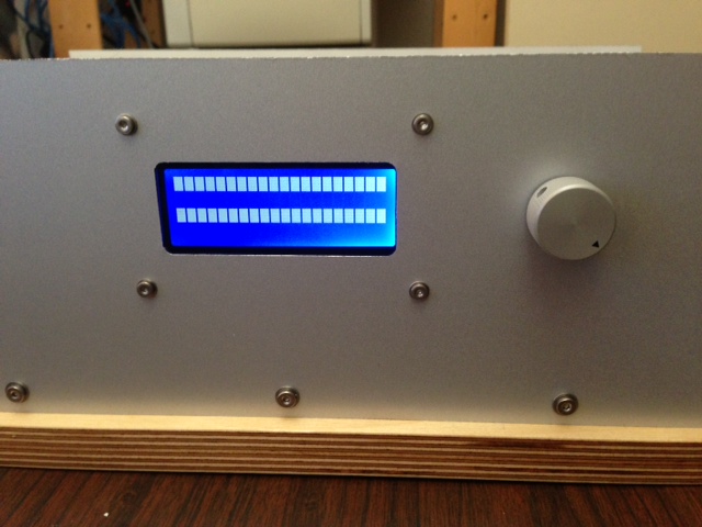
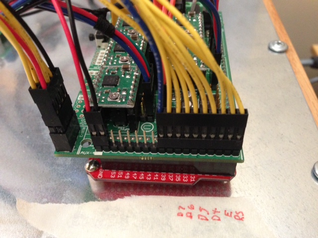
I'm having some trouble getting my 20x4 LCD (basically a homemade ultipanel clone) and my RAMPS 1.4 board talking. I am running the latest Marlin firmware. I am not able to get the LCD to display anything other than the "alternating rows of blocks" test pattern. Please see the attached photos for lcd image and connections.
I have been using justblair's connection schematic found here: [www.justblair.co.uk] and have triple checked that all of the indicated connections have continuity between the RAMPS board and the LCD.
Interestingly, the rotary encoder DOES appear to be working: when I push it I get the buzzer beep and when I blindly fiddle around with it and press the button, it will occasionally do things like activate the sd card reader. The sd card reader is connected but has no card in it yet.
I am running the latest version of the Marlin firmware (downloaded this morning). I have made only minimal changes to the config file at this point (basically just enough to get it to compile and start up without errors):
line 56: #define MOTHERBOARD 33
line 136: #define TEMP_SENSOR_0 7 // budaschnozzle
line 137: #define TEMP_SENSOR_1 0
line 138: #define TEMP_SENSOR_2 0
line 139: #define TEMP_SENSOR_BED 8 // trinity labs
line 395: #define ULTIPANEL //the ultipanel as on thingiverse
line 486: #define NEWPANEL //enable this if you have a click-encoder panel
When I run the downloaded firmware through serial monitor, I get:
start
echo: External Reset
Marlin 1.0.0
echo: Last Updated: Jul 7 2013 11:02:29 | Author: (none, default config)
Compiled: Jul 7 2013
echo: Free Memory: 4009 PlannerBufferBytes: 1232
echo:Hardcoded Default Settings Loaded
echo D init fail
I think my problem at this point has something to do with a bad configuration file, but I'm a bit at a loss as far as how to proceed with troubleshooting. For instance, at this stage it might be very useful to get the firmware to tell me exactly what settings (ie pins) it's trying to use for the LCD display, but I'm not sure how to go about doing that. I'm pretty new to arduinos.
Any ideas about what I should try next?
I have been using justblair's connection schematic found here: [www.justblair.co.uk] and have triple checked that all of the indicated connections have continuity between the RAMPS board and the LCD.
Interestingly, the rotary encoder DOES appear to be working: when I push it I get the buzzer beep and when I blindly fiddle around with it and press the button, it will occasionally do things like activate the sd card reader. The sd card reader is connected but has no card in it yet.
I am running the latest version of the Marlin firmware (downloaded this morning). I have made only minimal changes to the config file at this point (basically just enough to get it to compile and start up without errors):
line 56: #define MOTHERBOARD 33
line 136: #define TEMP_SENSOR_0 7 // budaschnozzle
line 137: #define TEMP_SENSOR_1 0
line 138: #define TEMP_SENSOR_2 0
line 139: #define TEMP_SENSOR_BED 8 // trinity labs
line 395: #define ULTIPANEL //the ultipanel as on thingiverse
line 486: #define NEWPANEL //enable this if you have a click-encoder panel
When I run the downloaded firmware through serial monitor, I get:
start
echo: External Reset
Marlin 1.0.0
echo: Last Updated: Jul 7 2013 11:02:29 | Author: (none, default config)
Compiled: Jul 7 2013
echo: Free Memory: 4009 PlannerBufferBytes: 1232
echo:Hardcoded Default Settings Loaded
echo
D init failI think my problem at this point has something to do with a bad configuration file, but I'm a bit at a loss as far as how to proceed with troubleshooting. For instance, at this stage it might be very useful to get the firmware to tell me exactly what settings (ie pins) it's trying to use for the LCD display, but I'm not sure how to go about doing that. I'm pretty new to arduinos.
Any ideas about what I should try next?
|
Re: LCD connection problems July 09, 2013 03:08AM |
Registered: 10 years ago Posts: 24 |
try to connect the lcd using this diagram
GND P1 -- GND
VCC P2 -- 5V
VLCD P3 -- 10K Trimpot
LCDRS P4 -- D16
GND P5 -- GND
LCDE P6 -- D17
LCD4 P11 -- D23
LCD5 P12 -- D25
LCD6 P13 -- D27
LCD7 P14 -- D29
P15 -- R1K 5v
GND P16 -- VCC
and in configuration define i leave yout the links for the schematics
#define REPRAP_DISCOUNT_SMART_CONTROLLER
[reprap.org]
[reprap.org]
|
Re: LCD connection problems July 14, 2013 02:16PM |
Registered: 10 years ago Posts: 2 |
Got it working. I plugged the LCD connections into my little Saleae logic analyzer and found that I was getting credible signals for E, RS, D4, D5, D6 and D7. After a bit of poking around in the LCD datasheet, it occurred to me that maybe the floating R/W pin was the problem. I went ahead and grounded that pin and everything seems to be working fine now.
Anyway, there might be some variation between LCDs as far as whether or not that pin needs to be set to ground in order for things to work, but in my case, I definitely needed it.
Anyway, there might be some variation between LCDs as far as whether or not that pin needs to be set to ground in order for things to work, but in my case, I definitely needed it.
Sorry, only registered users may post in this forum.