ABL einstellen Marlin
geschrieben von m3t00
|
ABL einstellen Marlin 02. May 2016 16:14 |
Registrierungsdatum: 7 Jahre zuvor Beiträge: 4 |
Hallo Leute 
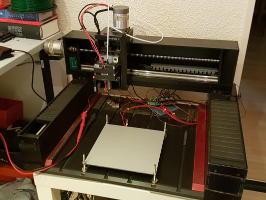
Ich habe in meiner Firma eine alte schön robuste CNC Graviermaschine vor dem Schrott gerettet
Was die Leute nicht alles wegschmeißen Egal, ich freu mich wie ein kleines Kind über mein neues Baby
Die Elektronik, die beinahe genauso groß war wie die "Fräse" selber, habe ich direkt ausgemustert und gegen mein Ramps 1.4 von meinem Prusa i2 ausgetauscht.
Als Software benutzte ich Repetier Host mit der aktuellsten Marlin Version (1.1.0-RC6 - 24 April 2016).
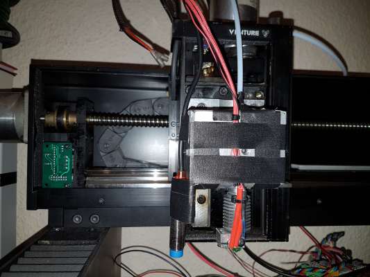
Schnell noch die Einstellungen angepasst (Endstops, Steps per Unit, Feedrate etc.) und die Halterung leicht modifiziert, sodass der Extruder und der indukt. Sensor erstmal halten.
Muss nur noch mein Heizbett wieder anschließen und den Extruder in Betrieb nehmen aber das geht ja flott.
Bis hierhin läuft alles wie es soll.
Jetzt zu meinem Problem
Wie muss ich das ABL einstellen?! Verstehe ich noch nicht so ganz
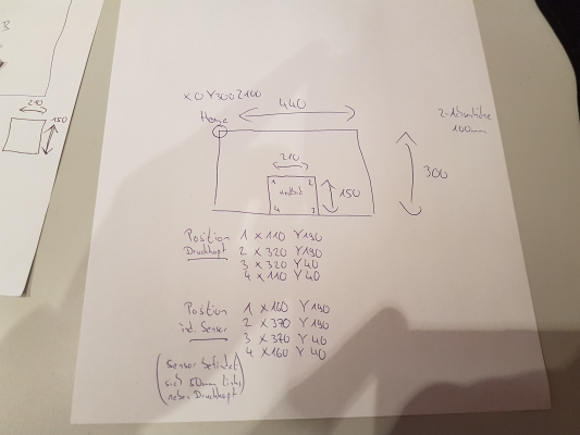
(Auf den Zettel habe ich einmal die ganzen maximalen Wegstrecken der einzelnen Achsen beschriftet und wo das Heizbett liegt etc.)
Wäre echt cool wenn ihr mir weiter helfen könnt.
1-mal bearbeitet. Zuletzt am 02.05.16 16:21.

Ich habe in meiner Firma eine alte schön robuste CNC Graviermaschine vor dem Schrott gerettet

Was die Leute nicht alles wegschmeißen
 Egal, ich freu mich wie ein kleines Kind über mein neues Baby
Die Elektronik, die beinahe genauso groß war wie die "Fräse" selber, habe ich direkt ausgemustert und gegen mein Ramps 1.4 von meinem Prusa i2 ausgetauscht.
Als Software benutzte ich Repetier Host mit der aktuellsten Marlin Version (1.1.0-RC6 - 24 April 2016).
Schnell noch die Einstellungen angepasst (Endstops, Steps per Unit, Feedrate etc.) und die Halterung leicht modifiziert, sodass der Extruder und der indukt. Sensor erstmal halten.
Muss nur noch mein Heizbett wieder anschließen und den Extruder in Betrieb nehmen aber das geht ja flott.
Bis hierhin läuft alles wie es soll.
Jetzt zu meinem Problem

Wie muss ich das ABL einstellen?! Verstehe ich noch nicht so ganz

(Auf den Zettel habe ich einmal die ganzen maximalen Wegstrecken der einzelnen Achsen beschriftet und wo das Heizbett liegt etc.)
Wäre echt cool wenn ihr mir weiter helfen könnt.

1-mal bearbeitet. Zuletzt am 02.05.16 16:21.
|
Re: ABL einstellen Marlin 02. May 2016 16:20 |
Registrierungsdatum: 7 Jahre zuvor Beiträge: 4 |
Die beiden Fettmakierten habe ich ausgeklammert und bei dem Schrägen weiß ich nicht wie das zu verstehen ist bzw welche Werte ich da nun genau für mich einsetzten muss 
Muss ich für´s ABL sonst noch was ändern außer diese 3 Sachen?
Meine Config aus dem AutoLvl.
1-mal bearbeitet. Zuletzt am 02.05.16 16:21.

Muss ich für´s ABL sonst noch was ändern außer diese 3 Sachen?
Meine Config aus dem AutoLvl.
Quote
m3t00
//===========================================================================
//============================ Bed Auto Leveling ============================
//===========================================================================
// @section bedlevel
#define AUTO_BED_LEVELING_FEATURE // Delete the comment to enable (remove // at the start of the line)
//#define DEBUG_LEVELING_FEATURE
#define Z_MIN_PROBE_REPEATABILITY_TEST // If not commented out, Z Probe Repeatability test will be included if Auto Bed Leveling is Enabled.
#if ENABLED(AUTO_BED_LEVELING_FEATURE)
// There are 2 different ways to specify probing locations:
//
// - "grid" mode
// Probe several points in a rectangular grid.
// You specify the rectangle and the density of sample points.
// This mode is preferred because there are more measurements.
//
// - "3-point" mode
// Probe 3 arbitrary points on the bed (that aren't collinear)
// You specify the XY coordinates of all 3 points.
// Enable this to sample the bed in a grid (least squares solution).
// Note: this feature generates 10KB extra code size.
#define AUTO_BED_LEVELING_GRID
#if ENABLED(AUTO_BED_LEVELING_GRID)
#define LEFT_PROBE_BED_POSITION 105
#define RIGHT_PROBE_BED_POSITION 105
#define FRONT_PROBE_BED_POSITION 75
#define BACK_PROBE_BED_POSITION 75
#define MIN_PROBE_EDGE 10 // The Z probe minimum square sides can be no smaller than this.
// Set the number of grid points per dimension.
// You probably don't need more than 3 (squared=9).
#define AUTO_BED_LEVELING_GRID_POINTS 2
#else // !AUTO_BED_LEVELING_GRID
// Arbitrary points to probe.
// A simple cross-product is used to estimate the plane of the bed.
#define ABL_PROBE_PT_1_X 15
#define ABL_PROBE_PT_1_Y 180
#define ABL_PROBE_PT_2_X 15
#define ABL_PROBE_PT_2_Y 20
#define ABL_PROBE_PT_3_X 170
#define ABL_PROBE_PT_3_Y 20
#endif // AUTO_BED_LEVELING_GRID
// Z Probe to nozzle (X,Y) offset, relative to (0, 0).
// X and Y offsets must be integers.
//
// In the following example the X and Y offsets are both positive:
// #define X_PROBE_OFFSET_FROM_EXTRUDER 10
// #define Y_PROBE_OFFSET_FROM_EXTRUDER 10
//
// +--- BACK ---+
// |.......................|
// L |......(+) P.........| R <-- probe (20,20)
// E |......................| I
// F |....(-) N (+)..... | G <-- nozzle (10,10)
// T |......................| H
// |.........(-)..........| T
// |.......................|
// O-- FRONT --+
// (0,0)
#define X_PROBE_OFFSET_FROM_EXTRUDER -50 // X offset: -left [of the nozzle] +right
#define Y_PROBE_OFFSET_FROM_EXTRUDER 0 // Y offset: -front [of the nozzle] +behind
#define Z_PROBE_OFFSET_FROM_EXTRUDER 0 // Z offset: -below [the nozzle] (always negative!)
#define XY_TRAVEL_SPEED 8000 // X and Y axis travel speed between probes, in mm/min.
#define Z_RAISE_BEFORE_PROBING 15 // How much the Z axis will be raised before traveling to the first probing point.
#define Z_RAISE_BETWEEN_PROBINGS 5 // How much the Z axis will be raised when traveling from between next probing points.
#define Z_RAISE_AFTER_PROBING 15 // How much the Z axis will be raised after the last probing point.
//#define Z_PROBE_END_SCRIPT "G1 Z10 F12000\nG1 X15 Y330\nG1 Z0.5\nG1 Z10" // These commands will be executed in the end of G29 routine.
// Useful to retract a deployable Z probe.
// Probes are sensors/switches that need to be activated before they can be used
// and deactivated after the use.
// Allen Key Probes, Servo Probes, Z-Sled Probes, FIX_MOUNTED_PROBE, ... . You have to activate one of these for the AUTO_BED_LEVELING_FEATURE
// A fix mounted probe, like the normal inductive probe, must be deactivated to go below Z_PROBE_OFFSET_FROM_EXTRUDER
// when the hardware endstops are active.
#define FIX_MOUNTED_PROBE
// A Servo Probe can be defined in the servo section below.
// An Allen Key Probe is currently predefined only in the delta example configurations.
//#define Z_PROBE_SLED // Enable if you have a Z probe mounted on a sled like those designed by Charles Bell.
//#define SLED_DOCKING_OFFSET 5 // The extra distance the X axis must travel to pickup the sled. 0 should be fine but you can push it further if you'd like.
// If you've enabled AUTO_BED_LEVELING_FEATURE and are using the Z Probe for Z Homing,
// it is highly recommended you leave Z_SAFE_HOMING enabled!
#define Z_SAFE_HOMING // Use the z-min-probe for homing to z-min - not the z-min-endstop.
// This feature is meant to avoid Z homing with Z probe outside the bed area.
// When defined, it will:
// - Allow Z homing only after X and Y homing AND stepper drivers still enabled.
// - If stepper drivers timeout, it will need X and Y homing again before Z homing.
// - Position the Z probe in a defined XY point before Z Homing when homing all axis (G28).
// - Block Z homing only when the Z probe is outside bed area.
#if ENABLED(Z_SAFE_HOMING)
#define Z_SAFE_HOMING_X_POINT ((X_MIN_POS + X_MAX_POS) / 2) // X point for Z homing when homing all axis (G28).
#define Z_SAFE_HOMING_Y_POINT ((Y_MIN_POS + Y_MAX_POS) / 2) // Y point for Z homing when homing all axis (G28).
#endif
#endif // AUTO_BED_LEVELING_FEATURE
1-mal bearbeitet. Zuletzt am 02.05.16 16:21.
|
Re: ABL einstellen Marlin 03. May 2016 02:13 |
Registrierungsdatum: 10 Jahre zuvor Beiträge: 513 |
Hallo und willkommen im Forum,
ich bastel gerade mit Marlin Version 1.1.0-RC5 rum und mein ABL funktioniert auch noch nicht so ganz, wie ich es mir vorstelle. Also sei vorsichtig bei meinen Ratschlägen ;-)
Was hast du in deiner Firmware für ein Größe der Durckfläche angegeben? 440 x 300?
Dann verstehe ich nur folgenden Teil deiner Einstellungen nicht
Hast du bei den langen Schrauben - die das Druckbett halten - keine Angst, da mal voll mit dem Hotend dagegen zu fahren?
Grüße
Martin
Grüße
Martin
ich bastel gerade mit Marlin Version 1.1.0-RC5 rum und mein ABL funktioniert auch noch nicht so ganz, wie ich es mir vorstelle. Also sei vorsichtig bei meinen Ratschlägen ;-)
Was hast du in deiner Firmware für ein Größe der Durckfläche angegeben? 440 x 300?
Dann verstehe ich nur folgenden Teil deiner Einstellungen nicht
#define LEFT_PROBE_BED_POSITION 105 #define RIGHT_PROBE_BED_POSITION 105 #define FRONT_PROBE_BED_POSITION 75 #define BACK_PROBE_BED_POSITION 75Damit liegen deine Messpunkte doch gar nicht auf deiner Druckfläche?
Hast du bei den langen Schrauben - die das Druckbett halten - keine Angst, da mal voll mit dem Hotend dagegen zu fahren?
Grüße
Martin
Grüße
Martin
|
Re: ABL einstellen Marlin 03. May 2016 06:33 |
Registrierungsdatum: 7 Jahre zuvor Beiträge: 4 |
Moin Martin,
erstmal danke
ja genau für X habe ich 440 und für Y 300 eingestellt. Das sind jetzt die maximal Wege die der Drucker fahren kann.
Mein Druckbereich beginnt aber erst auf der X-Achse ab 110 bis 320 und bei der Y Achse ab 40 bis 190.
Die Werte habe ich als letztes ausprobiert mit dem Gedankengang das ich vor G29 den Drucker in die Mitte des Druckbetts fahre und die jeweiligen Werte sind die Wege nach außen...Aber der Gedankengang war wohl falsch...
Hab am Anfang für links 110 (XAchse Druckbereich Anfang), rechts 320 (XAchse Druckbereich Ende), hinten 190 (Y ACHSE Druckbereich Anfang) und vorne 40 (Y ACHSE Druckbereich Ende) eingestellt - aber das haute auch nicht hin.
Wie soll man also das mit links, rechts, vorne & hinten denn verstehen? Vorallem von wo aus gesehen??
Bin leider ein wenig ratlos.
Mit den langen Schrauben ist es nur provisorisch, da ich es mal eben schnell testen wollte...(genauso wie meine Druckkopfhalterung)
LG Marcell
1-mal bearbeitet. Zuletzt am 03.05.16 11:08.
erstmal danke

ja genau für X habe ich 440 und für Y 300 eingestellt. Das sind jetzt die maximal Wege die der Drucker fahren kann.
Mein Druckbereich beginnt aber erst auf der X-Achse ab 110 bis 320 und bei der Y Achse ab 40 bis 190.
Die Werte habe ich als letztes ausprobiert mit dem Gedankengang das ich vor G29 den Drucker in die Mitte des Druckbetts fahre und die jeweiligen Werte sind die Wege nach außen...Aber der Gedankengang war wohl falsch...
Hab am Anfang für links 110 (XAchse Druckbereich Anfang), rechts 320 (XAchse Druckbereich Ende), hinten 190 (Y ACHSE Druckbereich Anfang) und vorne 40 (Y ACHSE Druckbereich Ende) eingestellt - aber das haute auch nicht hin.
Wie soll man also das mit links, rechts, vorne & hinten denn verstehen? Vorallem von wo aus gesehen??

Bin leider ein wenig ratlos.

Mit den langen Schrauben ist es nur provisorisch, da ich es mal eben schnell testen wollte...(genauso wie meine Druckkopfhalterung)
LG Marcell
1-mal bearbeitet. Zuletzt am 03.05.16 11:08.
|
Re: ABL einstellen Marlin 03. May 2016 15:31 |
Registrierungsdatum: 7 Jahre zuvor Beiträge: 4 |
Habe jetzt meinen Fehler gefunden 
Man gibt ja hier die Position vom Sensor zum Druckkopf an...(meiner befindet sich eben 50mm links neben dem Druckkopf)
#define X_PROBE_OFFSET_FROM_EXTRUDER -50 // X offset: -left [of the nozzle] +right
#define Y_PROBE_OFFSET_FROM_EXTRUDER 0 // Y offset: -front [of the nozzle] +behind
#define Z_PROBE_OFFSET_FROM_EXTRUDER 0 // Z offset: -below [the nozzle] (always negative!
Diese 50 hat er immer zusätzlich zu meinen Anfangseinstellungen (die an sich ja auch richtig waren) dazu gerechnet...
#define LEFT_PROBE_BED_POSITION 110
#define RIGHT_PROBE_BED_POSITION 320
#define FRONT_PROBE_BED_POSITION 40
#define BACK_PROBE_BED_POSITION 190
sodass er immer bei der Rechtsprobe mit 320 +50 gefahren ist und somit "fast" mit dem Druckkopf rechts an die Schienen gefahren ist.
Da ich es immer per Reset abgebrochen habe, ist mir kein Muster aufgefallen
Nunja aber danke Martin
PS: zu den langen Schrauben nochmal - da ich in Marlin und dem Startcode in Repetier Host die ganzen Verfahrenswege in der Maschine und dem Druckbett genau definiert habe, brauche ich auch keine Angst mehr zu haben. Einziges Manko, wenn ich es manuell ohne Startcode steuere dann kann menschliches Versagen eintreten
4-mal bearbeitet. Zuletzt am 03.05.16 15:38.

Man gibt ja hier die Position vom Sensor zum Druckkopf an...(meiner befindet sich eben 50mm links neben dem Druckkopf)
#define X_PROBE_OFFSET_FROM_EXTRUDER -50 // X offset: -left [of the nozzle] +right
#define Y_PROBE_OFFSET_FROM_EXTRUDER 0 // Y offset: -front [of the nozzle] +behind
#define Z_PROBE_OFFSET_FROM_EXTRUDER 0 // Z offset: -below [the nozzle] (always negative!
Diese 50 hat er immer zusätzlich zu meinen Anfangseinstellungen (die an sich ja auch richtig waren) dazu gerechnet...
#define LEFT_PROBE_BED_POSITION 110
#define RIGHT_PROBE_BED_POSITION 320
#define FRONT_PROBE_BED_POSITION 40
#define BACK_PROBE_BED_POSITION 190
sodass er immer bei der Rechtsprobe mit 320 +50 gefahren ist und somit "fast" mit dem Druckkopf rechts an die Schienen gefahren ist.
Da ich es immer per Reset abgebrochen habe, ist mir kein Muster aufgefallen

Nunja aber danke Martin

PS: zu den langen Schrauben nochmal - da ich in Marlin und dem Startcode in Repetier Host die ganzen Verfahrenswege in der Maschine und dem Druckbett genau definiert habe, brauche ich auch keine Angst mehr zu haben. Einziges Manko, wenn ich es manuell ohne Startcode steuere dann kann menschliches Versagen eintreten

4-mal bearbeitet. Zuletzt am 03.05.16 15:38.
|
Re: ABL einstellen Marlin 04. May 2016 01:34 |
Registrierungsdatum: 10 Jahre zuvor Beiträge: 513 |
In diesem Forum dürfen leider nur registrierte Teilnehmer schreiben.


