Z axis leaning
Posted by rkc
|
Z axis leaning January 04, 2015 06:07AM |
Registered: 9 years ago Posts: 42 |
Ever since I built it, the z axis on my Ormerod has leaned forwards somewhat. I printed the compensation piece and added the relevant line to my config.g:
M556 S78 X0 Y-1.0 Z-1.25 ; Put your axis compensation here
and this has worked well in terms of getting nice square prints. But it bothers me that it is so far out of true, and I keep thinking I should fix it. It might make it easier to get the bed properly levelled too...
However it's not clear to me how/if this angle can be adjusted or what would make it out of true. Any ideas/suggestions? Did anyone else find they needed such large values in the M556 settings?
Richard
|
Re: Z axis leaning January 04, 2015 07:53AM |
Registered: 10 years ago Posts: 14,672 |
What do you mean by "leaned forwards" - in which direction? I don't think it should be possible for it to lean significantly in the +X direction, because the Z extrusion sits squarely against the Y extrusion. However, if you have an Ormerod 1 and have not modified it to use a better bed support and three-point levelling, then it is quite likely that the bed is lower at the X=0 end than it is at the X=200 end. If that is the case, then I suggest you buy one of DaveK's aluminium bed supports.
Large delta printer [miscsolutions.wordpress.com], E3D tool changer, Robotdigg SCARA printer, Crane Quad and Ormerod
Disclosure: I design Duet electronics and work on RepRapFirmware, [duet3d.com].
Large delta printer [miscsolutions.wordpress.com], E3D tool changer, Robotdigg SCARA printer, Crane Quad and Ormerod
Disclosure: I design Duet electronics and work on RepRapFirmware, [duet3d.com].
|
Re: Z axis leaning January 04, 2015 09:05AM |
Registered: 10 years ago Posts: 1,230 |
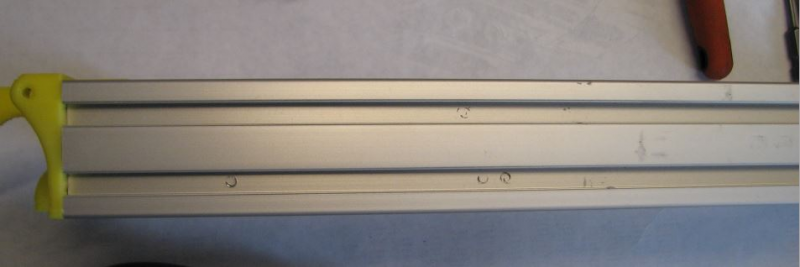
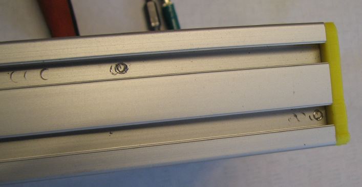
What David said - and you can easily see if the x-extrusion sits square up against the y-extrusion, you should not be able to slice a piece of paper in there, top or bottom, the extrusion should be held tight together, if you place your finger in the connection between the two and twist the axis you should not be able to feel any movement between these two
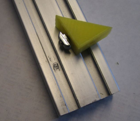
But notice, all the screws with the t-nuts that mount the x-extrusion may be too long and may bottom out against the y-extrusion instead of pulling both extrusions together, I did advice Ian RepRapPro about it long ago, but he said something like the too long screws was already out there and what can we do about it? - well make a note in the documentation of cause
Here the problem visualized:
If that should be the problem, shorten the screws a little - and you can make the z-axis even more stable by changing the z-corner-bracket for a small length of angled aluminium and ditto the z-foot with a slice of aluminium, in my latest re-build I chose to drill the extrusions and pull them together with a 4mm bolt and T-nut but that might be overkill
But as David said, the y-extrusion is supposed to be square to the z-extrusion and the x-axis is per design square to the z-extrusion and cannot be of more than a very tiny bit, so the last thing to do is to adjust the bed against the x-axis carrying the nozzle - with a 3-point adjusted bed, start with the inner screws, adjust until level as seen from the nozzle in the Y+- direction, then adjust the outer screw to get the bed level as seen from the nozzle in the X+- direction
..and then - if the bed do not seem to be square when you move the nozzle Y+- at the outer end of the bed - adjust your y-axis end parts (printed/acrylic)
Erik
|
Re: Z axis leaning January 04, 2015 10:21AM |
Registered: 9 years ago Posts: 42 |
It's an Ormerod 2.
I'm not sure exactly what is not square to what - the symptom is that after levelling the bed but without applying the M556 compensations, vertical prints come out rather a way off vertical - they lean slightly in both X and Y directions.
I was assuming all this lean came from the Z axis extrusion not being perpendicular to the Y axis extrusion, and I think that the Y part of the lean DOES come from that. I suppose the X part of the lean could also be caused if the X arm was not perpendicular to the Z axis. I can't see any gaps between the Z and Y extrusions (and as far as I can tell from a set square they are square to each other in the X direction) so I suppose it must be the x arm.
Richard
|
Re: Z axis leaning January 04, 2015 11:28AM |
Registered: 9 years ago Posts: 42 |
Ok, I tinkered some more and I am now 99% sure that the problem is in the X arm not the Z pillar. I adjusted the bed to be at exactly 90 degrees to the pillar, measured along the X axis (may not be what I would want for printing, but much easier to set accurately for the purposes of this test). I then adjusted the z height until I could just fit a measuring block under the bar at the X=200 end. I had to raise Z a further 1.3mm before I could fit that same block under the bar at the X=0 end.
I repeated the test checking the height to the bottom of the acrylic X beam, and it's the same - i.e. it's the whole X beam that is tilted up not just the bar within it.
Is there a way to adjust this?
Richard
I repeated the test checking the height to the bottom of the acrylic X beam, and it's the same - i.e. it's the whole X beam that is tilted up not just the bar within it.
Is there a way to adjust this?
Richard
|
Re: Z axis leaning January 04, 2015 12:54PM |
Registered: 10 years ago Posts: 14,672 |
1. Is there slight anticlockwise twist or wave in the acrylic X arm, as you view it from the open end of the X axis? This was a common problem on Ormerod 1 (not sure about Ormerod 2), and will cause the head to rotate a little about the X axis as it moves along the X axis; which in turn will cause the nozzle to rise and fall.
2. Is the Z smooth rod accurately parallel to the Z axis extrusion, or are they closer at the top than at the bottom?
3. Otherwise, check with a setsquare that the X arm is at right angles to the smooth rod. If not, you may be able to adjust the angle slightly if you slacken the bearing clamp screws, adjust, then re-tighten..
Large delta printer [miscsolutions.wordpress.com], E3D tool changer, Robotdigg SCARA printer, Crane Quad and Ormerod
Disclosure: I design Duet electronics and work on RepRapFirmware, [duet3d.com].
|
Re: Z axis leaning January 05, 2015 08:25AM |
Registered: 10 years ago Posts: 2,472 |
Quote
rkc
Ok, I tinkered some more and I am now 99% sure that the problem is in the X arm not the Z pillar. I adjusted the bed to be at exactly 90 degrees to the pillar, measured along the X axis (may not be what I would want for printing, but much easier to set accurately for the purposes of this test). I then adjusted the z height until I could just fit a measuring block under the bar at the X=200 end. I had to raise Z a further 1.3mm before I could fit that same block under the bar at the X=0 end.
I repeated the test checking the height to the bottom of the acrylic X beam, and it's the same - i.e. it's the whole X beam that is tilted up not just the bar within it.
Is there a way to adjust this?
Richard
The important thing is to ensure the Z axis ground rod is exactly square to the Y ground rods (the two Y axis rods must be exactly parallel), and the X axis ground rod is exactly square to the Y axis ground rods. These should be checked with a set-square. This will take care of the XY plane and the YZ plane. The XZ plane is much easier to adjust, because that is taken care of by adjusting the bed so that it is exactly parallel to the X-axis ground rod. If you do that, the X-Z angle will be 90 degrees as far as the print is concerned even if the X and Z rods are not quite square in the XZ plane. The only effect of having those rods off-square will be to make the Z height of the print an insignificant bit smaller. So simply adjust the bed so that the nozzle touches the bed at the same height at X=0 and X=200.
If you find that it is not possible to level the bed because when the back of the bed (X=0) is level in the Y plane (nozzle height the same at Y=0 and Y=200), the front of the bed (X=200) is not level, it means that the two Y ground rods are not parallel, and you need to slacken the bolts holding an acrylic arm and gently twist it up or down to get the rods parallel - in an extreme case you may need to print a new end piece (Y idler pulley holder) . If you get the 4 corners of the bed level but find the center of the bed is not the same height, it usually means that the acrylic X arm is twisted, though a small difference can be caused by Bowden tube pressure and other factors. If you get the height difference to less than 0.2mm over the whole bed it should be sufficient to produce good prints without needing any bed or axis compensation, which in my opinion is what you should aim for. This can only be achieved if you fit a better bed support than the MDF supplied with the Ormerod, otherwise you will have to adjust the bed for almost every print.
Dave
|
Re: Z axis leaning January 05, 2015 12:19PM |
Registered: 9 years ago Posts: 42 |
Very useful information - thanks!
I slackened off a few screws, checked with a set square, and retightened everything, and I am now in much better shape in general, though I have noticed (thanks to this and your other post in the other thread) that I have an issue with my Y rods not being parallel, so I'll have another go at getting that right next time I have a chance to tinker.
However I'm not sure I completely agree with you on this statement:
While I agree that you getting the bed and the X rod parallel is important (indeed, vital, or you won't be able to get your first layer to print properly), I think that if they are not perpendicular to Z then you will get a leaning model (unless corrected via M556), rather than just a shorter one. Imagine your X rod and bed both tilted up at 45 degrees - Z movements that were expected to be vertical would also have a substantial X component.
In my case, the slight angle between X and Z was corrected just by loosening the bolts attaching the X axis to the linear bearings, and retightening them after it had dropped a little under its own weight. It's now VERY close to perpendicular, and my test axes print reflects that. Certainly closer than it was.
Richard
I slackened off a few screws, checked with a set square, and retightened everything, and I am now in much better shape in general, though I have noticed (thanks to this and your other post in the other thread) that I have an issue with my Y rods not being parallel, so I'll have another go at getting that right next time I have a chance to tinker.
However I'm not sure I completely agree with you on this statement:
Quote
dmould
The XZ plane is much easier to adjust, because that is taken care of by adjusting the bed so that it is exactly parallel to the X-axis ground rod. If you do that, the X-Z angle will be 90 degrees as far as the print is concerned even if the X and Z rods are not quite square in the XZ plane. The only effect of having those rods off-square will be to make the Z height of the print an insignificant bit smaller. So simply adjust the bed so that the nozzle touches the bed at the same height at X=0 and X=200.
While I agree that you getting the bed and the X rod parallel is important (indeed, vital, or you won't be able to get your first layer to print properly), I think that if they are not perpendicular to Z then you will get a leaning model (unless corrected via M556), rather than just a shorter one. Imagine your X rod and bed both tilted up at 45 degrees - Z movements that were expected to be vertical would also have a substantial X component.
In my case, the slight angle between X and Z was corrected just by loosening the bolts attaching the X axis to the linear bearings, and retightening them after it had dropped a little under its own weight. It's now VERY close to perpendicular, and my test axes print reflects that. Certainly closer than it was.
Richard
|
Re: Z axis leaning January 06, 2015 07:14AM |
Registered: 10 years ago Posts: 2,472 |
Quote
rkc
Very useful information - thanks!
I slackened off a few screws, checked with a set square, and retightened everything, and I am now in much better shape in general, though I have noticed (thanks to this and your other post in the other thread) that I have an issue with my Y rods not being parallel, so I'll have another go at getting that right next time I have a chance to tinker.
However I'm not sure I completely agree with you on this statement:
Quote
dmould
The XZ plane is much easier to adjust, because that is taken care of by adjusting the bed so that it is exactly parallel to the X-axis ground rod. If you do that, the X-Z angle will be 90 degrees as far as the print is concerned even if the X and Z rods are not quite square in the XZ plane. The only effect of having those rods off-square will be to make the Z height of the print an insignificant bit smaller. So simply adjust the bed so that the nozzle touches the bed at the same height at X=0 and X=200.
While I agree that you getting the bed and the X rod parallel is important (indeed, vital, or you won't be able to get your first layer to print properly), I think that if they are not perpendicular to Z then you will get a leaning model (unless corrected via M556), rather than just a shorter one. Imagine your X rod and bed both tilted up at 45 degrees - Z movements that were expected to be vertical would also have a substantial X component.
In my case, the slight angle between X and Z was corrected just by loosening the bolts attaching the X axis to the linear bearings, and retightening them after it had dropped a little under its own weight. It's now VERY close to perpendicular, and my test axes print reflects that. Certainly closer than it was.
Richard
You are correct and I was indeed wrong - the X rod must be square to the Z rod. However the Z rod only has to be square to the bed in the XZ plane, not any other part of the printer, so any tilt in the X direction of the Z column is easiest fixed by adjusting the bed rather than the Z extrusion.
Dave
|
Re: Z axis leaning January 06, 2015 04:43PM |
Registered: 9 years ago Posts: 42 |
Quote
dmould
You are correct and I was indeed wrong - the X rod must be square to the Z rod. However the Z rod only has to be square to the bed in the XZ plane, not any other part of the printer, so any tilt in the X direction of the Z column is easiest fixed by adjusting the bed rather than the Z extrusion.
Dave
Agreed - squaring the bed to the Z axis is very easy (since there are nice flat areas to put the set square against, and adjusting screws provided). And then adjusting the X axis rod to be parallel to the bed is also quite straightforward if you just loosen the screws holding it and nudge it in the appropriate direction - a suitable square object placed on the bed acts as a height gauge.
I think there is a bit of a design flaw on the Ormerod 2 (or I followed some instructions incorrectly) in that as assembled it is very liable to warp the Y axis rods to be non-parallel, since the extrusion is supported at just one end. I fixed mine by placing a 5mm packing piece under each end of the extrusion and then screwing the entire thing down to a piece of 18mm ply (and fastening the front rod down to the ply using cable ties).
My Ormerod is now beautifully square in all directions (within a tenth of a millimetre on the bed level I think) and all is well.
Thanks again for all your help on this.
|
Re: Z axis leaning January 07, 2015 02:37AM |
Registered: 10 years ago Posts: 1,230 |
Quote
rkc
..I think there is a bit of a design flaw on the Ormerod 2 (or I followed some instructions incorrectly) in that as assembled it is very liable to warp the Y axis rods to be non-parallel, since the extrusion is supported at just one end. I fixed mine by placing a 5mm packing piece under each end of the extrusion and then screwing the entire thing down to a piece of 18mm ply (and fastening the front rod down to the ply using cable ties)...
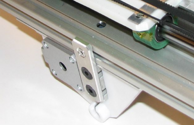
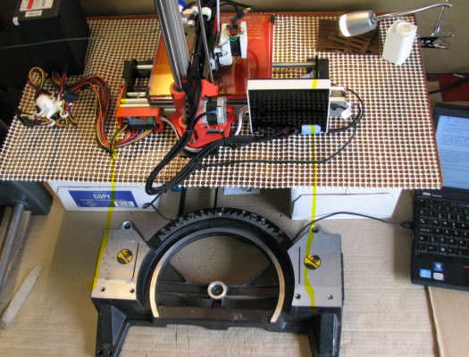
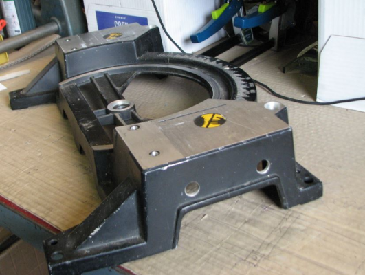
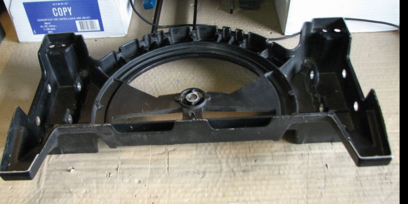
Yes, its a bit flimsy in that department and fixing the printer to anything solid and stable will fix that and also give something to hold on to while moving the printer - I was considering to mount the printer on this aluminium cast scrapyard find but never got around to it, notice the milled top, perfect for arresting the y-end parts to, the out-cuts at both sides to carry the printer, the holes in both sides to mount a filament holder - you cannot twist this design, its very solid - this came from an electric saw, easy to find something like this
Notice the filament could be mounted horizontal on a carousel under the printer and a small size power supply could fit right in one of the hollow side departments
Erik
Sorry, only registered users may post in this forum.
