Home
>
Reprappers
>
Topic
My Prusa build - Trials and Tribulations
Posted by iLikeWaffles
|
My Prusa build - Trials and Tribulations July 12, 2012 11:27AM |
Registered: 11 years ago Posts: 26 |
Probably best to start my own build thread so I can ask questions as I progress with my build.
I ended up buying parts from 6 different vendors on 3 continents, which has turned out to be a bit of a hassle.
Word of advice to anyone who wants to build one for the first time: buy a kit from a single vendor or purchase all your components from a single BOM and follow a single set of instructions.
There are conflicting instructions and material lists all over the place. Luckily, I figured out that a frankenprinter can be built no matter what type of parts you have, albeit with modifications to the parts.
I am attempting to build a Prusa Iteration 2 (i2) with parts for different versions and following a few sets of instructions. It’s all starting to make sense and I am starting to relax. I'm about 8 hours in.
I purchased my hardware kit from Ultimachine, which came with shorter rods cut for the original Prusa even though they say it works for i2. Well it will work after cutting a pair of the smooth rods from 420mm to 400mm (thanks NelsonRap).
The Prusa i2 wiki states…
My harware kit came with the following lenghts...
2 - M8 x 210mm zinc steel threaded rod
4 - M8 x 294mm zinc steel threaded rod
6 - M8 x 370mm zinc steel threaded rod
3 - M8 x 440mm zinc steel threaded rod
2 - 8mm x 350mm Stainless Steel Alloy 303, Precision Ground Bar
2 - 8mm x 406mm Stainless Steel Alloy 303, Precision Ground Bar
2 - 8mm x 420mm Stainless Steel Alloy 303, Precision Ground Bar
I assembled the frame triangles to the maximum length the 370mm rods would allow. Then using a caliper I jigged all triangle sides equally (~305mm from plastic to plastic in my case). I jigged all the horizontal frame distances to 234mm (all instructions seem to have this number for the horizontal distances).
I purchased my Y-bed setup from Ebay. This setup also appears to be for the original Prusa. So I had a new lower bed cut out of Plexiglas yesterday at a local glass shop. Will Plexiglas be alright so close to the heatbed (they didn’t know the heat properties)?
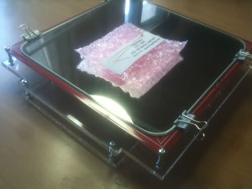
Here is the Y-bed setup I purchased from Ebay. I will only be using the heatbed and mirror from this kit as I already cut a new single bed as per Prusa's github instructions.
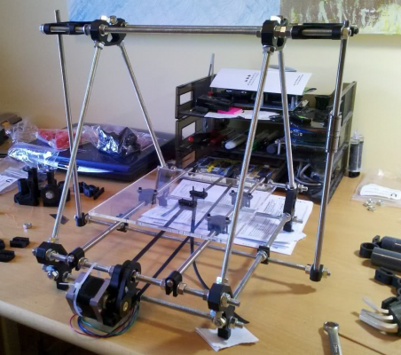
Here is how it sits today. Notice the 3 nuts on the top threaded rods to space out the Z motor mounts. I decided to cut the X carriage smooth rods instead of using the nuts. New pics to follow. I am also using printed 2 piece snap pulleys instead of the fender washers. I hear these are not as accurate due to imperfections in the printing process, but we’ll give them a shot. I am also using GT2 belts and pulleys.
I ended up buying parts from 6 different vendors on 3 continents, which has turned out to be a bit of a hassle.
Word of advice to anyone who wants to build one for the first time: buy a kit from a single vendor or purchase all your components from a single BOM and follow a single set of instructions.
There are conflicting instructions and material lists all over the place. Luckily, I figured out that a frankenprinter can be built no matter what type of parts you have, albeit with modifications to the parts.
I am attempting to build a Prusa Iteration 2 (i2) with parts for different versions and following a few sets of instructions. It’s all starting to make sense and I am starting to relax. I'm about 8 hours in.
I purchased my hardware kit from Ultimachine, which came with shorter rods cut for the original Prusa even though they say it works for i2. Well it will work after cutting a pair of the smooth rods from 420mm to 400mm (thanks NelsonRap).
The Prusa i2 wiki states…
Quote
In this manual it is assumed that the smooth rods are 405mm each. The resulting threaded rod lengths are:
1x 500mm - low center rod
2x 450mm - top rods
6x 400mm - frame vertex
4x 320mm - lower rods for front and back side
2x 250-300mm - Z smooth rods
My harware kit came with the following lenghts...
2 - M8 x 210mm zinc steel threaded rod
4 - M8 x 294mm zinc steel threaded rod
6 - M8 x 370mm zinc steel threaded rod
3 - M8 x 440mm zinc steel threaded rod
2 - 8mm x 350mm Stainless Steel Alloy 303, Precision Ground Bar
2 - 8mm x 406mm Stainless Steel Alloy 303, Precision Ground Bar
2 - 8mm x 420mm Stainless Steel Alloy 303, Precision Ground Bar
I assembled the frame triangles to the maximum length the 370mm rods would allow. Then using a caliper I jigged all triangle sides equally (~305mm from plastic to plastic in my case). I jigged all the horizontal frame distances to 234mm (all instructions seem to have this number for the horizontal distances).
I purchased my Y-bed setup from Ebay. This setup also appears to be for the original Prusa. So I had a new lower bed cut out of Plexiglas yesterday at a local glass shop. Will Plexiglas be alright so close to the heatbed (they didn’t know the heat properties)?
Here is the Y-bed setup I purchased from Ebay. I will only be using the heatbed and mirror from this kit as I already cut a new single bed as per Prusa's github instructions.
Here is how it sits today. Notice the 3 nuts on the top threaded rods to space out the Z motor mounts. I decided to cut the X carriage smooth rods instead of using the nuts. New pics to follow. I am also using printed 2 piece snap pulleys instead of the fender washers. I hear these are not as accurate due to imperfections in the printing process, but we’ll give them a shot. I am also using GT2 belts and pulleys.
|
Re: My Prusa build - Trials and Tribulations July 12, 2012 12:12PM |
Admin Registered: 17 years ago Posts: 7,879 |
I recommend making a heatshield like this: [reprap.org] to prevent any warping of the plexiglass. Even if it does not get hot enough to go soft the fact it is heated on one side only can make it curl a little and because the bearings are not attached near where the bed is a tiny amount of curl is significant.
[www.hydraraptor.blogspot.com]
[www.hydraraptor.blogspot.com]
|
Re: My Prusa build - Trials and Tribulations July 13, 2012 09:17AM |
Registered: 11 years ago Posts: 26 |
nophead Wrote:
-------------------------------------------------------
> I recommend making a heatshield like this:
> [reprap.org]
> t_Shield to prevent any warping of the plexiglass.
> Even if it does not get hot enough to go soft the
> fact it is heated on one side only can make it
> curl a little and because the bearings are not
> attached near where the bed is a tiny amount of
> curl is significant.
Ahh thanks for the suggestion. I made one last night, which you can see on the right in the picture.
More issues...
1. After cutting the X-axis smooth rods to 400mm they were still too long for the whole X-axis assembly to fit between the Z-axis smooth rods (after tightening the frame and plumbing the Z smooth rods). My X-ends do not have holes drilled all the way through so there is not adjustment. I had to loosen one side of the frame and space out the entire side. Now my horizontal jigging distance is 238mm. It is impossible to jig up the frame and plumb the Z rods and then install the X-axis in that order (with the parts I have). Unless I knew to jig the frame to 238mm.
My process was: I plumbed one of the Z smooth rods, loosened the other side of the frame and then installed the X axis. Ziptied the bearings and tightened everything down. I made sure everything slid smoothly and was parallel. I never plumbed the other side Z rod, but everything slides smoothly.
2. My Z shaft couplers are made for M4 hardware, which I did not receive enough of with the hardware kit. Not a huge problem.
3. The GT2 pulley I received from Lulzbot rubs agains the X-end-motor mount so I had to grind it down. The pulley is on the larger side at 36 teeth and I suspect a smaller one would be just fine.
My printed parts came with Z-axis stabilizers, but none of the instructions have them incorporated. I know now how they mount, but I will just wait till later to install them.
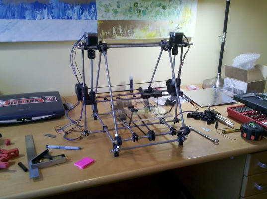
As it sits today...
-------------------------------------------------------
> I recommend making a heatshield like this:
> [reprap.org]
> t_Shield to prevent any warping of the plexiglass.
> Even if it does not get hot enough to go soft the
> fact it is heated on one side only can make it
> curl a little and because the bearings are not
> attached near where the bed is a tiny amount of
> curl is significant.
Ahh thanks for the suggestion. I made one last night, which you can see on the right in the picture.

More issues...
1. After cutting the X-axis smooth rods to 400mm they were still too long for the whole X-axis assembly to fit between the Z-axis smooth rods (after tightening the frame and plumbing the Z smooth rods). My X-ends do not have holes drilled all the way through so there is not adjustment. I had to loosen one side of the frame and space out the entire side. Now my horizontal jigging distance is 238mm. It is impossible to jig up the frame and plumb the Z rods and then install the X-axis in that order (with the parts I have). Unless I knew to jig the frame to 238mm.
My process was: I plumbed one of the Z smooth rods, loosened the other side of the frame and then installed the X axis. Ziptied the bearings and tightened everything down. I made sure everything slid smoothly and was parallel. I never plumbed the other side Z rod, but everything slides smoothly.
2. My Z shaft couplers are made for M4 hardware, which I did not receive enough of with the hardware kit. Not a huge problem.
3. The GT2 pulley I received from Lulzbot rubs agains the X-end-motor mount so I had to grind it down. The pulley is on the larger side at 36 teeth and I suspect a smaller one would be just fine.
My printed parts came with Z-axis stabilizers, but none of the instructions have them incorporated. I know now how they mount, but I will just wait till later to install them.
As it sits today...
|
Re: My Prusa build - Trials and Tribulations July 13, 2012 09:52AM |
Admin Registered: 17 years ago Posts: 7,879 |
Yes I could never see the logic in the push fit X ends. Saves a few screws but makes the rod lengths critical.
Are you sure the Z couplers are for M4? They look very much like the ones I designed, which are for M3.
[www.hydraraptor.blogspot.com]
Are you sure the Z couplers are for M4? They look very much like the ones I designed, which are for M3.
[www.hydraraptor.blogspot.com]
|
Re: My Prusa build - Trials and Tribulations July 13, 2012 10:14AM |
Registered: 11 years ago Posts: 26 |
nophead Wrote:
-------------------------------------------------------
> Are you sure the Z couplers are for M4? They look
> very much like the ones I designed, which are for
> M3.
They have nut traps and the only nut big enough to fit was an M4. I did have to drill the holes a little to push the M4 screws through. Also...rubber tubing is not required on the motor shaft as the inside of the coupler has two diameters to join the motor shaft and threaded rod. My motors shafts are keyed so there is no chance of slipping.
|
Re: My Prusa build - Trials and Tribulations July 13, 2012 10:58AM |
Admin Registered: 17 years ago Posts: 7,879 |
The tubing is to make the coupling flexible so any eccentricity or bend in the studding does not impart wobble to the X axis, not for grip, although it helps. See [hydraraptor.blogspot.co.uk].
If the nut traps are big relative to the holes it might be an SAE version rather than metric.
[www.hydraraptor.blogspot.com]
If the nut traps are big relative to the holes it might be an SAE version rather than metric.
[www.hydraraptor.blogspot.com]
|
Re: My Prusa build - Trials and Tribulations July 13, 2012 05:30PM |
Registered: 12 years ago Posts: 77 |
|
Re: My Prusa build - Trials and Tribulations July 13, 2012 10:47PM |
Registered: 12 years ago Posts: 313 |
nophead Wrote:
-------------------------------------------------------
> Yes I could never see the logic in the push fit X
> ends. Saves a few screws but makes the rod lengths
> critical.
You can very easily put the adjustment in the Z rod upper ends instead, like this (if you use the V1 420mm X smooth rods):
I don't even understand how you could do it any other way, I had to hammer the X smooth rods into the X ends and the Z rods would never be totally vertical unless you adjusted the vertex horizontal spacing to match the X end spacing..
|
Re: My Prusa build - Trials and Tribulations July 14, 2012 01:34AM |
Admin Registered: 17 years ago Posts: 7,879 |
Yes but both rods have to be exactly the same length or the ends will twist.
[www.hydraraptor.blogspot.com]
[www.hydraraptor.blogspot.com]
|
Re: My Prusa build - Trials and Tribulations July 16, 2012 12:16PM |
Registered: 12 years ago Posts: 19 |
Initially I was sceptical too about the blind push-fit ends on the x-axis as we had to use a lot of force to get the rods in. On the other hand, you do have to be very careful in tightening up the securing bolts with the version 1 x-ends. If they are not tight enough, the drive belt can pull the ends inwards; and if they are too tight, you risk cracking the plastic under the nut-traps.
I have been drilling the holes in the x-ends to 8mm so the rods fit in comfortably (or maybe 7.5mm might be better to still give a tighter interference fit?).
You definitely need the extra nut and washer to position the rear z-motor-mount to get a spacing that matches the now non-adjustable x axis width.
I've put together some notes and photos here regarding the difference between the Prusa v1 and the v2:
[reprapkit.com] wiki
(some of the notes here are not relevant if you don't have our kit with the 10mm wide belts, but most of them will be useful for anyone building any Prusa version 2).
|
Re: My Prusa build - Trials and Tribulations July 16, 2012 01:24PM |
Admin Registered: 17 years ago Posts: 7,879 |
Why do you use 10mm belts? Are they better than 6mm or is it just a sourcing issue?
[www.hydraraptor.blogspot.com]
[www.hydraraptor.blogspot.com]
|
Re: My Prusa build - Trials and Tribulations July 17, 2012 05:08AM |
Registered: 12 years ago Posts: 19 |
Leo did some calculations and concluded that these belts would suffer less stretch / bounce under high acceleration than the usual ones. I don't know whether the width is the main issue or the fact that he chose ones with steel tension reinforcements rather than plastic. I'll ask him and either come back or get him to do so.
Anyway, I'm pretty pleased with the quality of the prints we are getting event hough we've still a bit more fine tuning to do. Once we're satisfied with that and we've got past a few of our current targets, I'd be interested in having some sort of comparative print-out on different machine designs and settings to see if we can nail down the factors which really count.
Anyone else up for that?
|
Re: My Prusa build - Trials and Tribulations July 19, 2012 09:54AM |
Registered: 11 years ago Posts: 26 |
|
Re: My Prusa build - Trials and Tribulations July 19, 2012 11:34AM |
Registered: 13 years ago Posts: 643 |
|
Re: My Prusa build - Trials and Tribulations July 27, 2012 06:35PM |
Registered: 15 years ago Posts: 27 |
@nophead
You asked: Why 10mm?
I used the data from transdev.co.uk to model worst case* stretch for a Mendel style printer, and concluded that:
- Belt stretch can be enough to matter: 0.36mm in 5mm wide glass fibre and rubber HTD3.
- 10mm wide steel and polyurethane AT5 is ~1/3 as stretchy (~0.12mm).
I could have got another factor of 2 by going to 16mm wide ATL5, but that is less flexible so the minimum pulley size goes up, which makes for lower linear drive force at the relevant speeds, so lower usable axis acceleration.
AT5x10 seems optimal. I chose it for performance, but it's also a standard width in that profile, so it's easy to get.
Our kits use machined AT5 pulleys specifically designed to minimise backlash. The combination of belts and pulleys work well. I haven't yet had a chance to do an A/B test with a printer set up with (say) a GT2 belts. It's on my (long) list. :-)
* 1300mm belt, 0.5kg carriage moving away from motor and positioned right next to the motor, motor torque 0.43 Nm, minimum size specified drive pulley.
Leo
leo@RepRapKit.com
[RepRapKit.com]
|
Re: My Prusa build - Trials and Tribulations July 27, 2012 06:57PM |
Registered: 15 years ago Posts: 27 |
@iLikeWaffles
You asked about the double Z header on the RAMPS 1.4.
The header is wired with the two motors in parallel. I've concluded that you get better performance by wiring your Z motors in series.
You're better off doing the series wiring yourself and using one header.
I've tried it both ways, and series does work better with high current motors (which are common).
Here's why:
The most common motors used in RepRap are 1.68A NEMA17 steppers. The stepper driver for RAMPS often struggles to give more than 1.2A (depending on how well cooled it is), and certainly can't give the 3.36A required to drive two steppers in parallel at max torque. Wired in parallel your motor performance is heavily limited by the available drive current.
On the other hand, if you wire them in series they only need 1.68A to achieve max torque, and you're likely to get twice the pull-out torque you'd get from the parallel wiring. Nothing comes for free: Series wiring requires twice the voltage at any given step rate. Is this a problem? Not really: In our application we only need low RPM on Z, and we have loads of spare voltage anyway.
If anything, we have too much voltage (as nophead wrote), an we'll actually get more precise movement from a series wired Z axis.
I hope this helps.
Leo
leo@RepRapKit.com
[RepRapKit.com]
|
Re: My Prusa build - Trials and Tribulations August 08, 2012 09:30PM |
Registered: 11 years ago Posts: 26 |
Thanks for all the info guys.
I finally finished a week ago and did my first print. It was not bad for a first print without a heat bed and minimal calibration. It definitely wasn't a blob...
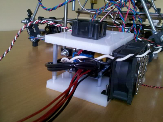
I finally got my heat bed issues taken care of. The problem was that it was shutting off after 15 seconds due to overheating on the RAMPS board. My heat bed is .75Ω so it draws 16A. I made an enclosure with fans for the RAMPS and all is good. Am able to heat the bed to 110°C and keep it there for hours without issues.
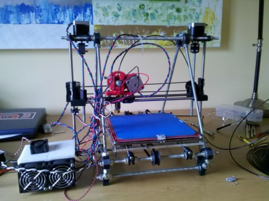
Here is how it sits right now.
I will try to add some z-stabilizers and print a filament spool holder soon.
Quick question on editing software...
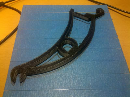
I was trying to print this wrench, but it is not fully flat. Is there a way in netfabb or something to add support structure for the area that is suspended in air. The author is using a makerbot and ReplicatorG, but I don't think the resulting gcode will work for me. There is a feature in ReplicatorG to add "support structure."
|
Re: My Prusa build - Trials and Tribulations August 09, 2012 09:01PM |
Registered: 11 years ago Posts: 26 |
Ok I have a huge problem(s)...
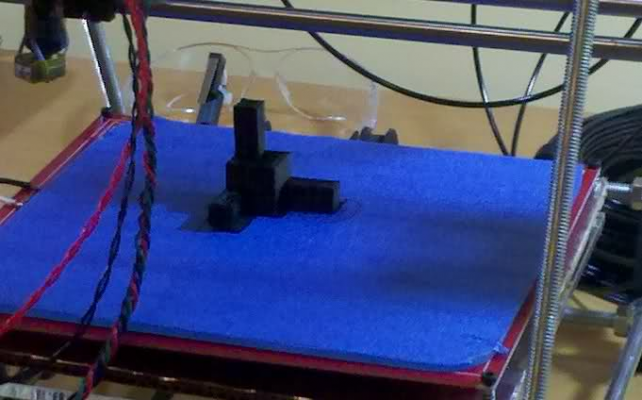
1. Why does my first layer y-axis offset on some prints, as you can see from the print below?
2. What should I do about melted extruder base?
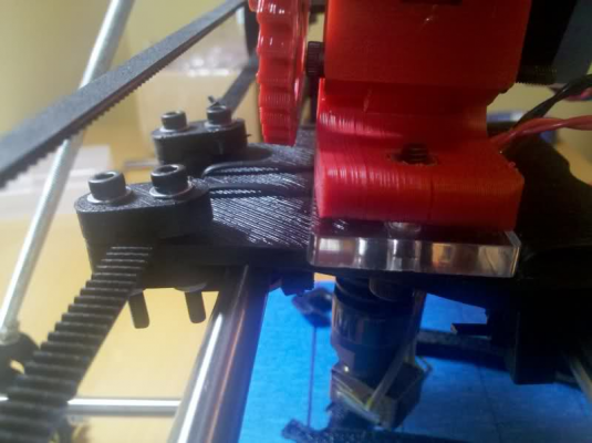
At first I noticed the print is slowly offsetting so I thought the issue was related to my first layer problem, but then noticed the extruder/hot-end was tilted pretty good. The combination of the heatbed and extruder temps probably melted the x-carriage.
Should I just use aluminum foil around the hot-end and and x-carriage bottom? Fans?
Can't really see much in the below pic, but the extruder was definitely lifting up and tilting. The weight of the motor was pulling it. The x-carriage was mush like a boxers face after 12 rounds. It also doesn't help to have 2 screws holding the whole thing together on the center line. Hmmmmmmm.
|
Re: My Prusa build - Trials and Tribulations August 09, 2012 09:37PM |
Admin Registered: 15 years ago Posts: 1,470 |
If your carriage and extruder are PLA you have to have a fan blowing over the thermal break of the hot end. If you are printing PLA it is also a good idea as it will lessen the chance of your extruder jamming because the filament softens too far up the hot end.
|
Help improve the RepRap wiki!
Just click "Edit" in the top-right corner of the page and start typing. Anyone can edit the wiki! |
|
Re: My Prusa build - Trials and Tribulations August 10, 2012 02:44AM |
Registered: 14 years ago Posts: 3,742 |
Hey, I recognize that filament spool holder! 
Bob Morrison
Wörth am Rhein, Germany
"Luke, use the source!"
BLOG - PHOTOS - Thingiverse

Bob Morrison
Wörth am Rhein, Germany
"Luke, use the source!"
BLOG - PHOTOS - Thingiverse
|
Re: My Prusa build - Trials and Tribulations August 10, 2012 09:27AM |
Registered: 11 years ago Posts: 26 |
NewPerfection Wrote:
-------------------------------------------------------
> If your carriage and extruder are PLA you have to
> have a fan blowing over the thermal break of the
> hot end. If you are printing PLA it is also a
> good idea as it will lessen the chance of your
> extruder jamming because the filament softens too
> far up the hot end.
Thanks for the info. I will be printing strictly ABS for a while since I have a huge spool of it.
My x-carriage is printed in PLA and has a mount for a 40mm fan. Never noticed it. Guess I will have to add a fan and try again.
rhmorrison Wrote:
-------------------------------------------------------
> Hey, I recognize that filament spool holder!
Yup, I finally was able to edit and save the STL so that it will fit on my bed. Can’t wait to actually print them. Thanks! Estimated time is 4.5 hours each.
-------------------------------------------------------
> If your carriage and extruder are PLA you have to
> have a fan blowing over the thermal break of the
> hot end. If you are printing PLA it is also a
> good idea as it will lessen the chance of your
> extruder jamming because the filament softens too
> far up the hot end.
Thanks for the info. I will be printing strictly ABS for a while since I have a huge spool of it.
My x-carriage is printed in PLA and has a mount for a 40mm fan. Never noticed it. Guess I will have to add a fan and try again.
rhmorrison Wrote:
-------------------------------------------------------
> Hey, I recognize that filament spool holder!

Yup, I finally was able to edit and save the STL so that it will fit on my bed. Can’t wait to actually print them. Thanks! Estimated time is 4.5 hours each.

|
Re: My Prusa build - Trials and Tribulations August 13, 2012 10:38AM |
Registered: 11 years ago Posts: 26 |
I installed a fan on the x-carriage, but then my hot-end temps would not go above 210°C. Turns out the fan was too strong so I downsized and all seems ok.
Now I’m trying to iron out little details to get good prints.
1. I think I have to slow down the print speeds from the default slic3r settings. The plastic just doesn’t stick good enough in some spots when this thing is flying around too fast.
2. I have a 0.35mm hotend and am using 0.25mm layer height. I think I have to go lower to get better results. 0.20 or 0.15mm?
3. When the hotend has to stop and transition to another poition on the print the plastic is not extruded right away. This issue is my biggest problem. Which setting can help this? When it transitions to another spot I feel like it should pause there for a fraction of a second to get the plastic flowing again. This problem is compounded on a long print and ruins it.
Sorry, only registered users may post in this forum.
