Homing works calibration doesn't.....
Posted by Sash
|
Homing works calibration doesn't..... August 17, 2015 12:07PM |
Registered: 8 years ago Posts: 30 |
Hi again,
Well I have made some progress as homing works.
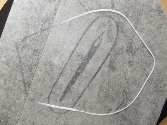
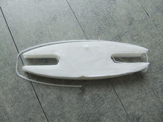
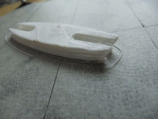
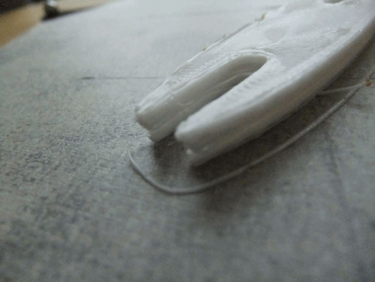
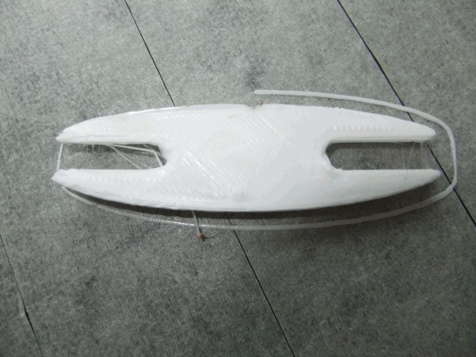
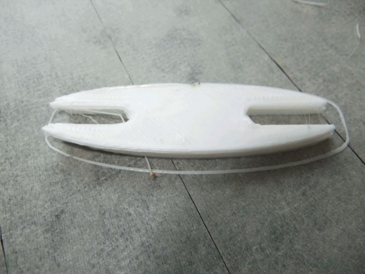
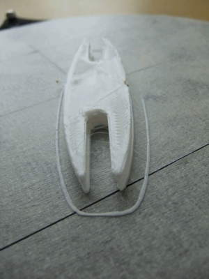
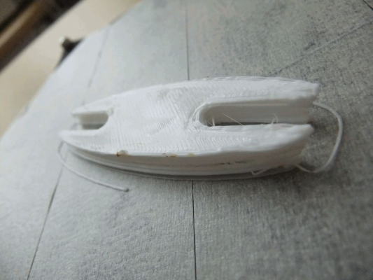
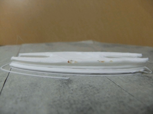
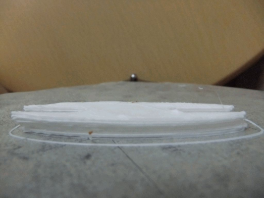
I cannot seem to calibrate my bed though enough to get printing well. I have managed a couple of descent prints. Generally though I can't print. I home and then use 'bed7' macro to calibrate the bed. It goes through the motions. On first pass it drags on areas of the build platform then second time I run bed7 it's fine no dragging. I run bed7 about 6 times before trying to print. But as you can see from the photo that the head still drags on the platform when trying to print. If I do get pass this stage and continue printing the bed will move sideways with the force of the head and the print will be misshapen. Any ideas would be welcome?
Cheers
Sash
|
Re: Homing works calibration doesn't..... August 17, 2015 12:30PM |
Registered: 10 years ago Posts: 14,672 |
Hi Sash,
I suggest you take a look at the section on the auto calibration file at [reprap.org]. In particular:
1. Use 6-point calibration, not 7 point.
2. After running it several times, copy the parameters to the M665 and M666 commands in config.g. Then it should no longer drag the nozzle across the bed when you run it.
3. Create a macro file called e,g, "Check bed" similar to bed.g but with S-1 on the final G30 command, to probe the bed and print the height errors without changing anything. Let us know what it reports.
Large delta printer [miscsolutions.wordpress.com], E3D tool changer, Robotdigg SCARA printer, Crane Quad and Ormerod
Disclosure: I design Duet electronics and work on RepRapFirmware, [duet3d.com].
|
Re: Homing works calibration doesn't..... August 17, 2015 01:50PM |
Registered: 8 years ago Posts: 30 |
Quote
dc42
Hi Sash,
I suggest you take a look at the section on the auto calibration file at [reprap.org]. In particular:
1. Use 6-point calibration, not 7 point.
2. After running it several times, copy the parameters to the M665 and M666 commands in config.g. Then it should no longer drag the nozzle across the bed when you run it.
3. Create a macro file called e,g, "Check bed" similar to bed.g but with S-1 on the final G30 command, to probe the bed and print the height errors without changing anything. Let us know what it reports.
Thanks for replying! Here is my results:
6:26:56 PM M98 P/macros/calcbed.g
Bed probe heights: 0.146 -0.164 0.154 -0.129 0.123 -0.106 -0.029, mean -0.001, deviation from mean 0.129
6:24:50 PM G32
Calibrated 6 factors using 7 points, deviation before 0.141 after 0.128
6:22:49 PM G32
Calibrated 6 factors using 7 points, deviation before 0.269 after 0.130
6:20:46 PM Calibrated 6 factors using 7 points, deviation before 2.925 after 0.092
6:20:24 PM G32
Error: Z probe warning: probe already triggered at start of probing move
Here is my bed.g modified to prevent destruction to my platform:
;M561
G31 X0 Y0                       ; don't want any probe offset for this
;G28
; Probe the bed and do 6-factor auto calibration
G1 X-49.00 Y-33.00 F500
G4 P300
G30 P0 X-49.00 Y-33.00 Z-99999    ; X tower
G4 P300
G1 X0 Y-60 F500
G4 P300
G30 P1 X0 Y-60 Z-99999          ; between X and Y towers
G4 P300
G1 X58 Y-32 F500     ; Y tower
G4 P300
G30 P2 X58 Y-32 Z-99999     ; Y tower
G4 P300
G1 X60 Y23 F500
G4 P300
G30 P3 X60 Y23 Z-99999        ; between Y and Z towers
G4 P300
G1 X0 Y60 F500
G4 P300
G30 P4 X0 Y60 Z-99999           ; Z tower
G4 P300
G1 X-58 Y32 F500
G4 P300
G30 P5 X-58 Y32 Z-99999       ; between Z and X towers
G4 P300
G1 X0 Y0 F500
G30 P6 X0 Y0 Z-99999 S6         ; centre, and auto-calibrate 6 factors
|
Re: Homing works calibration doesn't..... August 17, 2015 04:33PM |
Registered: 10 years ago Posts: 14,672 |
It appears to me that either your bed switches or your homing switches are giving very variable results. Try running calcbed.g several times, without any intervening G32 commands, to hee how reproducible the combination of homing switches + bed switches is. Then comment out the G28 command at the start of calcbed.g and run it again several times, to see how reproducible the bed switches are by themselves.
Edited 1 time(s). Last edit at 08/17/2015 04:33PM by dc42.
Large delta printer [miscsolutions.wordpress.com], E3D tool changer, Robotdigg SCARA printer, Crane Quad and Ormerod
Disclosure: I design Duet electronics and work on RepRapFirmware, [duet3d.com].
Edited 1 time(s). Last edit at 08/17/2015 04:33PM by dc42.
Large delta printer [miscsolutions.wordpress.com], E3D tool changer, Robotdigg SCARA printer, Crane Quad and Ormerod
Disclosure: I design Duet electronics and work on RepRapFirmware, [duet3d.com].
|
Re: Homing works calibration doesn't..... August 18, 2015 03:18AM |
Registered: 8 years ago Posts: 30 |
Quote
dc42
It appears to me that either your bed switches or your homing switches are giving very variable results. Try running calcbed.g several times, without any intervening G32 commands, to hee how reproducible the combination of homing switches + bed switches is. Then comment out the G28 command at the start of calcbed.g and run it again several times, to see how reproducible the bed switches are by themselves.
Thanks again for replying. So here is my set of results for the homing switches + bed switches combination:
7:54:24 AM Bed probe heights: 1.416 1.701 3.301 3.996 4.000 2.557 2.559, mean 2.790, deviation from mean 0.953
7:54:03 AM M98 P/MACROS/CALCBED.G
Error: Z probe warning: probe already triggered at start of probing move
7:51:50 AM Bed probe heights: 1.427 1.712 3.301 4.007 4.000 2.557 2.582, mean 2.798, deviation from mean 0.950
7:51:29 AM M98 P/MACROS/CALCBED.G
Error: Z probe warning: probe already triggered at start of probing move
7:49:32 AM Bed probe heights: 1.450 1.747 3.324 4.019 4.000 2.592 2.604, mean 2.819, deviation from mean 0.942
7:49:10 AM M98 P/MACROS/CALCBED.G
Error: Z probe warning: probe already triggered at start of probing move
7:47:03 AM Bed probe heights: 1.450 1.758 3.324 4.007 4.000 2.569 2.604, mean 2.816, deviation from mean 0.939
7:46:42 AM M98 P/MACROS/CALCBED.G
Error: Z probe warning: probe already triggered at start of probing move
7:44:25 AM Bed probe heights: 1.461 1.781 3.335 4.019 4.000 2.592 2.627, mean 2.831, deviation from mean 0.934
7:44:04 AM M98 P/MACROS/CALCBED.G
Error: Z probe warning: probe already triggered at start of probing move
Here are my results for bed switches alone (no homing with G28):
8:03:22 AM Bed probe heights: 1.930 2.055 3.312 3.916 4.000 3.003 2.787, mean 3.000, deviation from mean 0.758
8:03:02 AM M98 P/MACROS/CALCBED.G
Error: Z probe warning: probe already triggered at start of probing move
8:01:52 AM Bed probe heights: 1.930 2.067 3.312 3.939 4.000 3.003 2.787, mean 3.005, deviation from mean 0.760
8:01:31 AM M98 P/MACROS/CALCBED.G
Error: Z probe warning: probe already triggered at start of probing move
8:00:14 AM Bed probe heights: 1.278 1.667 3.289 3.996 4.000 2.546 2.524, mean 2.757, deviation from mean 0.988
7:59:52 AM M98 P/MACROS/CALCBED.G
Error: Z probe warning: probe already triggered at start of probing move
7:58:39 AM Bed probe heights: 1.278 1.678 3.289 3.996 4.000 2.557 2.536, mean 2.762, deviation from mean 0.986
7:58:18 AM M98 P/MACROS/CALCBED.G
Error: Z probe warning: probe already triggered at start of probing move
7:57:04 AM Bed probe heights: 1.290 1.678 3.301 3.984 4.000 2.557 2.547, mean 2.765, deviation from mean 0.982
7:56:43 AM M98 P/MACROS/CALCBED.G
Error: Z probe warning: probe already triggered at start of probing move
|
Re: Homing works calibration doesn't..... August 18, 2015 03:34AM |
Registered: 10 years ago Posts: 14,672 |
You need to get rid of that error message. I am assuming that you have the M666 X Y Z parameters all set to zero. You have huge initial calibration errors, and the nozzle is dragging on the bed at one point when probing (the point that is giving the 4mm height error).
First, I suggest you increase the Z dive height. This is set by the H parameter of the M558 command in config.g. The default is 4mm, but you need to increase that until you have the calibration error sorted out.
Second, fix the calibration error. I think your homing switches are triggering at different heights.
Edited 2 time(s). Last edit at 08/18/2015 03:36AM by dc42.
Large delta printer [miscsolutions.wordpress.com], E3D tool changer, Robotdigg SCARA printer, Crane Quad and Ormerod
Disclosure: I design Duet electronics and work on RepRapFirmware, [duet3d.com].
|
Re: Homing works calibration doesn't..... August 19, 2015 05:02AM |
Registered: 8 years ago Posts: 30 |
Quote
dc42
You need to get rid of that error message. I am assuming that you have the M666 X Y Z parameters all set to zero. You have huge initial calibration errors, and the nozzle is dragging on the bed at one point when probing (the point that is giving the 4mm height error).
First, I suggest you increase the Z dive height. This is set by the H parameter of the M558 command in config.g. The default is 4mm, but you need to increase that until you have the calibration error sorted out.
Second, fix the calibration error. I think your homing switches are triggering at different heights.
My config.g M666 is unchanged at:
M666 X0.0 Y0.0 Z0.0
Following your suggestion I amended the config.g M558 command to:
M558 P4 X0 Y0 Z0 H6
Then I re-ran the tests. So here is my set of results for the homing switches + bed switches combination:
>>>g28
SENDING:G28
>>>M98 P/MACROS/CALCBED.G
SENDING:M98 P/MACROS/CALCBED.G
Bed probe heights: 0.523 -0.082 -0.218 -0.483 -0.245 -0.452 -0.359, mean -0.188, deviation from mean 0.318
>>>g28
SENDING:G28
>>>M98 P/MACROS/CALCBED.G
SENDING:M98 P/MACROS/CALCBED.G
Bed probe heights: 0.523 -0.082 -0.195 -0.574 -0.199 -0.052 -0.119, mean -0.100, deviation from mean 0.301
>>>g28
SENDING:G28
>>>M98 P/MACROS/CALCBED.G
SENDING:M98 P/MACROS/CALCBED.G
Bed probe heights: 0.523 -0.082 -0.206 -0.574 -0.199 -0.064 -0.130, mean -0.105, deviation from mean 0.301
>>>g28
SENDING:G28
>>>M98 P/MACROS/CALCBED.G
SENDING:M98 P/MACROS/CALCBED.G
Bed probe heights: 0.511 -0.082 -0.206 -0.574 -0.210 -0.064 -0.130, mean -0.108, deviation from mean 0.299
>>>g28
SENDING:G28
>>>M98 P/MACROS/CALCBED.G
SENDING:M98 P/MACROS/CALCBED.G
Bed probe heights: 0.488 -0.082 -0.206 -0.586 -0.233 -0.075 -0.141, mean -0.119, deviation from mean 0.295
Here are my results for bed switches alone (no homing with G28):
>>>M98 P/MACROS/CALCBED.G
SENDING:M98 P/MACROS/CALCBED.G
Bed probe heights: 0.420 -0.082 -0.206 -0.586 -0.233 -0.075 -0.141, mean -0.129, deviation from mean 0.276
>>>M98 P/MACROS/CALCBED.G
SENDING:M98 P/MACROS/CALCBED.G
Bed probe heights: 0.488 -0.094 -0.206 -0.586 -0.233 -0.075 -0.141, mean -0.121, deviation from mean 0.295
>>>M98 P/MACROS/CALCBED.G
SENDING:M98 P/MACROS/CALCBED.G
Bed probe heights: 0.477 -0.094 -0.218 -0.597 -0.245 -0.075 -0.141, mean -0.128, deviation from mean 0.296
>>>M98 P/MACROS/CALCBED.G
SENDING:M98 P/MACROS/CALCBED.G
Bed probe heights: 0.408 -0.116 -0.218 -0.597 -0.233 -0.075 -0.153, mean -0.141, deviation from mean 0.275
>>>M98 P/MACROS/CALCBED.G
SENDING:M98 P/MACROS/CALCBED.G
Bed probe heights: 0.408 -0.116 -0.206 -0.586 -0.222 -0.075 -0.153, mean -0.136, deviation from mean 0.271
|
Re: Homing works calibration doesn't..... August 19, 2015 09:54AM |
Registered: 10 years ago Posts: 14,672 |
Those don't look too bad, although the homing switch of the tower by the first probe point is triggering about 0.5mm lower than the other two. However, there is a big change from the values you had before - they had height errors in the range of about 2mm to 4mm, now you have height errors in the range 0.5 to -0.6mm, which is much better. So I think you must have changed something else apart from the M558 H parameter.
Anyway, you should be able to run your bed.g file and get good calibration.
Large delta printer [miscsolutions.wordpress.com], E3D tool changer, Robotdigg SCARA printer, Crane Quad and Ormerod
Disclosure: I design Duet electronics and work on RepRapFirmware, [duet3d.com].
Anyway, you should be able to run your bed.g file and get good calibration.
Large delta printer [miscsolutions.wordpress.com], E3D tool changer, Robotdigg SCARA printer, Crane Quad and Ormerod
Disclosure: I design Duet electronics and work on RepRapFirmware, [duet3d.com].
|
Re: Homing works calibration doesn't..... August 19, 2015 02:28PM |
Registered: 8 years ago Posts: 30 |
Thanks again.
Well I proceeded to run bed.g several times here is the output:
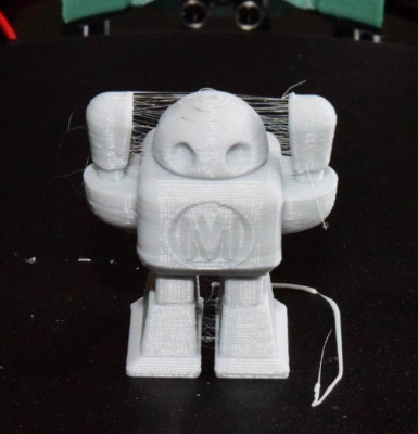
I used a simple test print file. Here is the result (a little disappointing):
Well I proceeded to run bed.g several times here is the output:
>>>g28
SENDING:G28
>>>g32
SENDING:G32
Calibrated 6 factors using 7 points, deviation before 0.196 after 0.169
>>>g32
SENDING:G32
Calibrated 6 factors using 7 points, deviation before 0.164 after 0.164
>>>g32
SENDING:G32
Calibrated 6 factors using 7 points, deviation before 0.172 after 0.167
>>>g32
SENDING:G32
Calibrated 6 factors using 7 points, deviation before 0.177 after 0.164
I used a simple test print file. Here is the result (a little disappointing):
|
Re: Homing works calibration doesn't..... August 19, 2015 03:48PM |
Registered: 10 years ago Posts: 14,672 |
The deviation is higher than I would expect, although I don't know what is typical for a Fisher. I notice that you are not allowing for different Z probe trigger heights at different XY positions, which RepRapPro now recommends. You can set these using the H parameter on the G30 commands if you are using my 1.09e firmware, or using G31 Zxx commands prior to the G30 commands in earlier firmware versions.
However, I think you should still be able to get reasonable prints. I suggest you look at your slicer settings, in particular speeds and temperatures.
Large delta printer [miscsolutions.wordpress.com], E3D tool changer, Robotdigg SCARA printer, Crane Quad and Ormerod
Disclosure: I design Duet electronics and work on RepRapFirmware, [duet3d.com].
|
Re: Homing works calibration doesn't..... August 20, 2015 03:43AM |
Registered: 8 years ago Posts: 68 |
I have build 4 Fishers for myself, work, and colleages at work (with another 3 to come). The first one has been rebuilt from scratch twice, as has my own one - I felt there were certain shortcomings with the assembly instructions that would otherwise enable a near perfect geometry at first build attempt. Using the knowledge gained from the first builds (and rebuilds), the last two I built reported an initial deviation of just less than 1 mm on initial calibration and then calibrated to a deviation of less than 50 um within 5 iterations. The deviation on my own one is now ~20 um. The first printer is back in pieces ready to be rebuilt as the others were but with a few additional modifications as it's going to be moved around a lot. What I'm getting at here is that it's very possible to get great calibration with almost no additional effort, its just a case of making sure thing are correct at build time. I'll post here later with some of the key things to check. I also plan on rebuilding the first printer from scratch this weekend, so I'll document my build method for those who are interested.
In the mean time, I would say that until you get the deviation below 0.09, don't even consider putting filament in the machine unless you're only printing tiny footprint parts in the centre of the bed. The initial robot test print is a little misleading as it's very possible to print this while having a very sub-optimal calibration and therefore can give a false indication of a printer that is well built and setup.
FWIW, despite the fact that the arm length should in theory be 160 mm, I have found so far that all 4 machines have required that I set the arm length to 162 mm. Doing this, the printers are then dimensionally accurate and also calibrate better and in fewer iterations. I know there will be people who will insist something is wrong and that it should be set to 160, but frankly, all 4 of my printers print better than the Stratasys Dimension I have at work.
|
Re: Homing works calibration doesn't..... August 20, 2015 05:23AM |
Registered: 8 years ago Posts: 443 |
Quote
bluesign2k
I also plan on rebuilding the first printer from scratch this weekend, so I'll document my build method for those who are interested.
I'll be building one next week... printing parts as I speak....VERY interested!
RepRapPro Mendel 3 Tricolour
RepRapPro Fisher
-Carbon Arms
-Easy adjust Carriage+effector
-axis stiffness mods
HE3D -600 delta
-Duet 0.8.5
-PanelDue
-DC42 Height probe
-RobotDigg metal components
Simplyfy3D
RS Design Spark CAD
|
Re: Homing works calibration doesn't..... August 20, 2015 02:37PM |
Registered: 8 years ago Posts: 30 |
Quote
bluesign2k
but frankly, all 4 of my printers print better than the Stratasys Dimension I have at work.
Reading this did lift my spirits as I was getting very disheartened with the build given the calibrations problems I have noted in a another post.
It seems to me that the crucial thing to get right is end-stop position, each idler assemblage equally positioned on its carriage rods so that the distance from the end-stop to the platform is equal on all three towers. I read that the algorithm for calibration starts with the assumption that this distance is set and defined. I guess much like the rod lengths. Naturally if these inputs are not accurate then the output cannot be either.
Quote
bluesign2k
I also plan on rebuilding the first printer from scratch this weekend, so I'll document my build method for those who are interested.
I second that, would very useful and interesting.
|
Re: Homing works calibration doesn't..... August 23, 2015 10:08AM |
Registered: 8 years ago Posts: 68 |
Cool. Well if someone finds any of it useful then at least I'm not wasting my time. I did the stripdown & re-build yesterday/today. I've made notes of what I did and any changes with some relevant pics... I'll tidy it up and get here here when I get some free time.
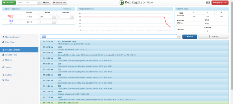
In the mean time, here's a screenshot of the initial calibration and first print. I'm pretty happy with that, tbh. Yeh, it's stringy, but that's the material rather then the printer.
In the mean time, here's a screenshot of the initial calibration and first print. I'm pretty happy with that, tbh. Yeh, it's stringy, but that's the material rather then the printer.
|
Re: Homing works calibration doesn't..... August 23, 2015 10:25PM |
Registered: 8 years ago Posts: 443 |
Your use of 162mm for arm length interests me, its clearly working by the end results, but it has to be compensating for another error or inaccuracy somewhere.
Something Id be interested in your build is the dimensions across each pair of balls and between each pair of balls balls on the effector and towers.... 12 measurements in total.. the tower measurements may just be possible with a 150mm caliper, but you have to make sure the measured carriages are at the same height.
Ideally the 6 across measurements will be identical, the 3 between measurements on the effector should be identical and the 3 between measurements on the tower should be identical, from these measurements I can calculate the effective radius, which from drawings I've already theoretically calculated at 80.3mm, but since these dimensions are subject to the manufacturing tolerances of the printed and laser cut parts, cap screws and the balls I suspect may actually have a significant degree of variation.
I suspect that what will be found is your effective radius will be scaled by a factor of 81/80 it certainly looks to be larger in that magnitude, which pythagorus then implies there is a similar scaling effect in the vertical axes, Id be surprised if there was an error in the pulse per mm factor, but that's the area where its pointing.
RepRapPro Mendel 3 Tricolour
RepRapPro Fisher
-Carbon Arms
-Easy adjust Carriage+effector
-axis stiffness mods
HE3D -600 delta
-Duet 0.8.5
-PanelDue
-DC42 Height probe
-RobotDigg metal components
Simplyfy3D
RS Design Spark CAD
|
Re: Homing works calibration doesn't..... August 24, 2015 03:47AM |
Registered: 8 years ago Posts: 68 |
Yeh, tell me about it! Weird, ey? I've read the pdf for the maths behind delta printers and agree that it really should be 160 mm. However, I'm now wondering whether theres something it neglects. The original reason we bought the Fisher (at work), aside from the price, was to use it as a reference to understand them - I have a big (huge?) delta with a >1 m build height that I was struggling to calibrate as well as I wanted. That printer also requires me to set the arm lengths to something significantly larger than their actual length in order to get correctly dimensioned output - indeed, on the order of ~50 mm larger!
Some of the measurements you ask for are tricky to make as the printer is a bit small to get calipers in... I'll try at work later. In the meantime, I can tell you that the outside ball spacing on each carriage and end effector are all ~57 mm with the difference between the biggest and smallest of <0.5 mm. I know that, because I spent the best part of 3 hours carefully filing the screws to get them to that tollerance. It's well worth the hassle of doing this as I found as delivered, they're miles out and makes all the difference if you're striving to get a flat build plane. Frankly, I think it's the biggest fault with the printer and RRP would do well to look at the QC of the tapping of the balls.
Interestingly, I left the head and carriages on a table in the sun yesterday while having lunch. When I went back to them the distance had increased on all of them by almost 300 um.
I'm curious to see how much of the deviation reported by the calibration is down to the bed itself being flat. All the 4 printers I've assembled so far have had one side that is almost flat and the other side it totally awful! I have a glass bed to try, but I haven't yet found a suitable way to modify the existing bed to accommodate it. I'm considering a thick polycarbonate bed with the centre milled down a few mm for the glass to sit in...
|
Re: Homing works calibration doesn't..... August 24, 2015 05:21AM |
Registered: 8 years ago Posts: 443 |
I derived the math from first principles so it will be interesting to see how they match up
I'm in the process of building mine as we speak and have just tuned all the carriages to 55.7mm
Ive just done a loose fit of the effector and these are the dimensions I'm looking at....
57.66 56.76 57.3
20.07 20.86 19.78
I think I'm going to dremmel these down to match the 55.7mm of the carriages
btw remind me to thank RRP for sending me an untapped ball!
RepRapPro Mendel 3 Tricolour
RepRapPro Fisher
-Carbon Arms
-Easy adjust Carriage+effector
-axis stiffness mods
HE3D -600 delta
-Duet 0.8.5
-PanelDue
-DC42 Height probe
-RobotDigg metal components
Simplyfy3D
RS Design Spark CAD
|
Re: Homing works calibration doesn't..... August 24, 2015 10:34PM |
Registered: 8 years ago Posts: 443 |
I've generated a model of a delta machine in Excel and have been running some scenarios with the 162mm arms and base scaled and the Z axis displacement correct and got some interesting results.
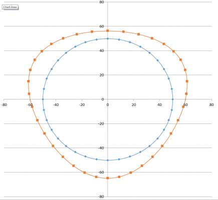
This chart compares a perfect 100mm circle on a perfectly calibrated machine (blue trace) with a machine with oversized arms (orange trace)
In order to better visualise the error on the orange trace I've multiplied it by 100, and found that it produces an interesting shape, its called a lobe its actually one of my favorite shapes because it has a very interesting property, that a casual inspection with calipers would convince you that its actually round...if you have a British 50p coin try it.... its also a shape that I used to anticipate with dread when working on machines, because it generally means your spindle bearings are knackered!
If you were to make both shapes and measure them with a pair of calipers the 100mm shape would measure 100mm (of course!), and the lobed shape would measure 100.21mm, which may be within a margin of error.
To detect a lobed shape you need to measure it with a three point measurement technique such as a placing it in a v-block and measuring the height as the shape is rotated.
It would be interesting to know if your printer with its oversized arms is actually printing lobes instead of cylinders.
Of course this doesn't mean this calibration technique is bad, if it enables parts to be produced within an acceptable margin of error then great, but it would be good to know if the actual consequence matches the prediction, if it doesn't then there is something else going on.
RepRapPro Mendel 3 Tricolour
RepRapPro Fisher
-Carbon Arms
-Easy adjust Carriage+effector
-axis stiffness mods
HE3D -600 delta
-Duet 0.8.5
-PanelDue
-DC42 Height probe
-RobotDigg metal components
Simplyfy3D
RS Design Spark CAD
|
Re: Homing works calibration doesn't..... August 25, 2015 03:28AM |
Registered: 8 years ago Posts: 68 |
Is this assuming that the arms themselves are oversized? My arms are definitely 160 mm from hole to hole.
I'll try to get those measurements for you today. I'll do a set of bed probes before and after some calibration cycles with the arms set to 160 mm and 162 mm. I'll use the glass bed to ensure there's minimal error from bed non-uniformity. I'll also print a couple of 100 mm diameter rings and see what shapes come out. I think I know where there might be able to find a v block to measure them...
I'll try to get those measurements for you today. I'll do a set of bed probes before and after some calibration cycles with the arms set to 160 mm and 162 mm. I'll use the glass bed to ensure there's minimal error from bed non-uniformity. I'll also print a couple of 100 mm diameter rings and see what shapes come out. I think I know where there might be able to find a v block to measure them...
|
Re: Homing works calibration doesn't..... August 25, 2015 05:16AM |
Registered: 8 years ago Posts: 443 |
nope it assumes that your arms are the correct length 160mm and your programmed arm length is 162mm, Im also assuming that your effective radius is actuall about 80.3mm and not the measurement your calibration is showing
RepRapPro Mendel 3 Tricolour
RepRapPro Fisher
-Carbon Arms
-Easy adjust Carriage+effector
-axis stiffness mods
HE3D -600 delta
-Duet 0.8.5
-PanelDue
-DC42 Height probe
-RobotDigg metal components
Simplyfy3D
RS Design Spark CAD
RepRapPro Mendel 3 Tricolour
RepRapPro Fisher
-Carbon Arms
-Easy adjust Carriage+effector
-axis stiffness mods
HE3D -600 delta
-Duet 0.8.5
-PanelDue
-DC42 Height probe
-RobotDigg metal components
Simplyfy3D
RS Design Spark CAD
|
Re: Homing works calibration doesn't..... August 25, 2015 09:53AM |
Registered: 8 years ago Posts: 68 |
Okay, so it's not exactly what you were after, but it's still pretty interesting...
I used a few pieces of Kapton tape to secure a borosilicate bed w/ Buildtak on top of the existing, cleaned bed. I reset the printer geometry back to the default:
I printed a 100 mm diameter ring with a 10 mm wall. The ring is circular and the average diameter is 99.93 mm and the average wall width is 10.12 mm.
I'll have to try this on my own machine tonight, but at this point I'm happy to concede that for a well setup machine, using an arm length of 160 mm is probably the best. While this machine has now had the most time spent on it in terms of making sure it's assembled I wonder whether the flatness of the bed plays a bigger part in the calibration that I first thought.
I used a few pieces of Kapton tape to secure a borosilicate bed w/ Buildtak on top of the existing, cleaned bed. I reset the printer geometry back to the default:
M665	Diagonal 160.00, delta radius 81.00, homed height 180.00, bed radius 75.0, X 0.00°, Y 0.00°, Z 0.00°
M666	Endstop adjustments X0.00 Y0.00 Z0.00
Then did a 7 point probe (x, z opposite, y, x opposite, z, y opposite, centre):
Bed probe heights: 3.665 2.770 2.727 2.336 2.430 2.753 2.682, mean 2.766, deviation from mean 0.399After a few 10 point, 6 factor calibrations which ended up with a deviation of 0.066 - this is the only time I've ever seen the deviation below ~100 um setting 160 mm arms. The new settings it found were:
M665	Diagonal 160.00, delta radius 81.70, homed height 177.10, bed radius 75.0, X -0.03°, Y 0.64°, Z 0.00°
M666	Endstop adjustments X-0.70 Y0.19 Z0.51
With the 7 point probe now giving:
Bed probe heights: 0.069 -0.038 0.060 -0.085 0.012 -0.081 0.125, mean 0.009, deviation from mean 0.075
I printed a 100 mm diameter ring with a 10 mm wall. The ring is circular and the average diameter is 99.93 mm and the average wall width is 10.12 mm.
I'll have to try this on my own machine tonight, but at this point I'm happy to concede that for a well setup machine, using an arm length of 160 mm is probably the best. While this machine has now had the most time spent on it in terms of making sure it's assembled I wonder whether the flatness of the bed plays a bigger part in the calibration that I first thought.
|
Re: Homing works calibration doesn't..... August 25, 2015 10:14PM |
Registered: 8 years ago Posts: 443 |
Using the sub bed is interesting, and points to a theory I've got...
One of the other effects the over dimensioned arms has on the kinematics is it creates a domed effect, i.e. as the effector moves in the XY plane at a constant Z height the toolpoint actually varies in Z height.....it also puts a significant offset into the Z positions, but this is easy to iron out by adjusting offsets.
Something that's been concerning me about the plate and switches on the Fisher, is that the magnitude of force and Z displacement required to activate the switch is greater in the centre of the plate than at the edge, and also varies around the edge itself.... plus there is also a bending moment in the plate itself, a very small lever effect caused by the relative position of the springs and plate and the greater force required at the centre may cause the arm to flex more, all adding up to inaccuracies when doing this kind of contact probing.
It is actually very easy to calculate the force difference using moment equations, if it takes 100g (1N) force acting directly on a spring to activate it then it will take 300g (3N) at the centre of the plate and 200g (2N) at a position half way between any two springs, whats less easy to calculate is the effect of these forces, but I suspect that at the edge where the one arm pair is nearly vertical the bending effect will be much lower than at the centre... plus the bending moment on the plate.... its a perfect storm, of increased force and reduced stiffness!
So, what I'm wondering is if when probing the controller is actually seeing the flat plate as being dished, and the domed effect caused by your over-dimensioned arms cancels this out.
If this is the case then adding your plate will have two positive effects, firstly it will stiffen the plate, and secondly the increased plate mass will reduce the magnitude of force required to break the switch.
Also, if this is the case and we can put a figure to the magnitude of the effect then we could feasibly use the variable height probing factor on the G30 to cancel it out.
Edited 1 time(s). Last edit at 08/26/2015 01:03AM by bgkdavis.
RepRapPro Mendel 3 Tricolour
RepRapPro Fisher
-Carbon Arms
-Easy adjust Carriage+effector
-axis stiffness mods
HE3D -600 delta
-Duet 0.8.5
-PanelDue
-DC42 Height probe
-RobotDigg metal components
Simplyfy3D
RS Design Spark CAD
|
Re: Homing works calibration doesn't..... August 26, 2015 02:50AM |
Registered: 8 years ago Posts: 443 |
Quote
bluesign2k
M665	Diagonal 160.00, delta radius 81.70, homed height 177.10, bed radius 75.0, X -0.03°, Y 0.64°, Z 0.00°
M666	Endstop adjustments X-0.70 Y0.19 Z0.51
Interesting to compare this to your earlier calibration where you have delta radius of 82.75 and homed height of 179.43 when you used the 162 measurement
By my model these figures would correct to 82.75*160/162= 81.73 and 179.43*160/162=177.21, which is damn near spot on what they actually calibrated to.
RepRapPro Mendel 3 Tricolour
RepRapPro Fisher
-Carbon Arms
-Easy adjust Carriage+effector
-axis stiffness mods
HE3D -600 delta
-Duet 0.8.5
-PanelDue
-DC42 Height probe
-RobotDigg metal components
Simplyfy3D
RS Design Spark CAD
Sorry, only registered users may post in this forum.
