Endstop issue
Posted by Sixaxix9
|
Endstop issue February 15, 2019 04:11AM |
Registered: 5 years ago Posts: 7 |
Hi eveyone! I'm Marco, first post here. I've been 3d printing for a couple of years with commercial printers, and today I've just finished the assebly of my last 3d printer. It is completely custom built, including the electronics. All works fine, and I'm pretty happy with it, but I'm having some issues with the endstops. I set up my board file, starting with the declaration of
I've checked with an oscilloscope the input pins, and they follow the switches correctly, but on Pronterface with the command M119 I see the endstops never triggered.
Casually, I tried to attach one endstop on pin 25, and it correctly triggers endstop Y. Is there any know issue about this? Tryed on Marlin 1.1.9, bugfix and also 2.0
Thanks!
EDIT:
I reflashed the code with the PINS_DEBUGGING enabled and ran M43, here the output, which is correct:
Edited 1 time(s). Last edit at 02/15/2019 04:24AM by Sixaxix9.
#define X_STOP_PIN        31
#define Y_STOP_PIN        30
#define Z_STOP_PIN        29
And then, in Configuration.h
#define USE_XMIN_PLUG
#define USE_YMIN_PLUG
#define USE_ZMIN_PLUG
//#define USE_XMAX_PLUG
//#define USE_YMAX_PLUG
//#define USE_ZMAX_PLUG

// Enable pullup for all endstops to prevent a floating state
//#define ENDSTOPPULLUPS //THERE ARE EXTERNAL PULLUPS ALREADY
Since I only have min endstops and I've used external 10k pullup resistor.
I've checked with an oscilloscope the input pins, and they follow the switches correctly, but on Pronterface with the command M119 I see the endstops never triggered.
Casually, I tried to attach one endstop on pin 25, and it correctly triggers endstop Y. Is there any know issue about this? Tryed on Marlin 1.1.9, bugfix and also 2.0
Thanks!
EDIT:
I reflashed the code with the PINS_DEBUGGING enabled and ran M43, here the output, which is correct:
PIN:  29   Port: A5        Z_MIN_PIN                   protected
.                          Z_STOP_PIN                  protected
PIN:  30   Port: A6        Y_MIN_PIN                   protected
.                          Y_STOP_PIN                  protected
PIN:  31   Port: A7        X_MIN_PIN                   protected
.                          X_STOP_PIN                  protected
Edited 1 time(s). Last edit at 02/15/2019 04:24AM by Sixaxix9.
|
Re: Endstop issue February 15, 2019 04:55AM |
Admin Registered: 13 years ago Posts: 7,002 |
|
Re: Endstop issue February 15, 2019 05:43AM |
Registered: 5 years ago Posts: 7 |
|
Re: Endstop issue February 15, 2019 06:39AM |
Registered: 5 years ago Posts: 7 |
Update here! Fuses were set correctly, and running "M43 I" on pronterface (it shows the protected pin status) reports correct readings for endstop pins. However, running M119 still gets wrong "open" or "TRIGGERED". I think this might be a software bug, is it worth to open an issue on GitHub?
|
Re: Endstop issue February 15, 2019 07:26AM |
Admin Registered: 13 years ago Posts: 7,002 |
are you saying its just inverted?
as that is just a setting
// Mechanical endstop with COM to ground and NC to Signal uses "false" here (most common setup).
#define X_MIN_ENDSTOP_INVERTING false // set to true to invert the logic of the endstop.
#define Y_MIN_ENDSTOP_INVERTING false // set to true to invert the logic of the endstop.
#define Z_MIN_ENDSTOP_INVERTING false // set to true to invert the logic of the endstop.
#define X_MAX_ENDSTOP_INVERTING false // set to true to invert the logic of the endstop.
#define Y_MAX_ENDSTOP_INVERTING false // set to true to invert the logic of the endstop.
#define Z_MAX_ENDSTOP_INVERTING false // set to true to invert the logic of the endstop.
It is very unlikely to be a bug, its a very basic part of the code...
what type of endstop are you using? just a mechanical switch from the pin to gnd?
you say you have a pull up, so endstop disconnected (or open) will be seen as 5v and connected will be seen as zero
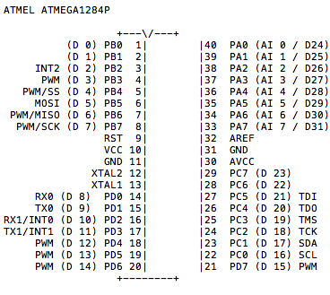
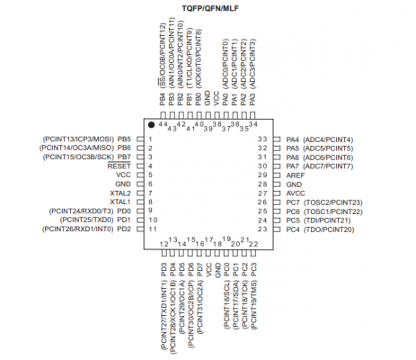
are you sure you really have it plugged into ardunio pin 29,30,31 ie physical pin numbers 35,34,33 respectively?
or pins 32,31 and 30 on TQFP
Edited 1 time(s). Last edit at 02/15/2019 07:38AM by Dust.
|
Re: Endstop issue February 15, 2019 08:24AM |
Registered: 5 years ago Posts: 7 |
Hi Dust, thanks for replying! Well, even if they need to be inverted they should toggle the endstop status anyway. But when I send M119 the endstop status never changes whatever the switch is open or closed.
Yes, they are the classic mechanical switches with external pull-up and debouncing capacitor (I've tryed other pins that don't have this circuit, and the problem is the same).
I am 100% sure that the pins are correct because when I send "M43 I" I receive the correct status of each pin, but when I send "M119" the endstop status never changes.
Edited 1 time(s). Last edit at 02/15/2019 08:25AM by Sixaxix9.
|
Re: Endstop issue February 15, 2019 09:15AM |
Admin Registered: 13 years ago Posts: 7,002 |
That is very weird
I looked into fastio_644.h (also does 1284p) and it shows a different table
where the ports D24-D31 are reversed on PA7-PA0
want to try an experiment?
your endstops are on 29,30 and 31, what is on 26.25 and 24 can you redefine any endstop to any of those pins and try it with m119? (while leaving the endstops electrically connected to where they are)
Edited 3 time(s). Last edit at 02/15/2019 09:23AM by Dust.
I looked into fastio_644.h (also does 1284p) and it shows a different table
/**                       ATMega644
 *
 *                        +---\/---+
 *            (D 0) PB0  1|        |40  PA0 (AI 0 / D31)
 *            (D 1) PB1  2|        |39  PA1 (AI 1 / D30)
 *       INT2 (D 2) PB2  3|        |38  PA2 (AI 2 / D29)
 *        PWM (D 3) PB3  4|        |37  PA3 (AI 3 / D28)
 *        PWM (D 4) PB4  5|        |36  PA4 (AI 4 / D27)
 *       MOSI (D 5) PB5  6|        |35  PA5 (AI 5 / D26)
 *       MISO (D 6) PB6  7|        |34  PA6 (AI 6 / D25)
 *        SCK (D 7) PB7  8|        |33  PA7 (AI 7 / D24)
 *                  RST  9|        |32  AREF
 *                  VCC 10|        |31  GND
 *                  GND 11|        |30  AVCC
 *                XTAL2 12|        |29  PC7 (D 23)
 *                XTAL1 13|        |28  PC6 (D 22)
 *       RX0 (D 8)  PD0 14|        |27  PC5 (D 21) TDI
 *       TX0 (D 9)  PD1 15|        |26  PC4 (D 20) TDO
 *  INT0 RX1 (D 10) PD2 16|        |25  PC3 (D 19) TMS
 *  INT1 TX1 (D 11) PD3 17|        |24  PC2 (D 18) TCK
 *       PWM (D 12) PD4 18|        |23  PC1 (D 17) SDA
 *       PWM (D 13) PD5 19|        |22  PC0 (D 16) SCL
 *       PWM (D 14) PD6 20|        |21  PD7 (D 15) PWM
 *                        +--------+
 */
where the ports D24-D31 are reversed on PA7-PA0
want to try an experiment?
your endstops are on 29,30 and 31, what is on 26.25 and 24 can you redefine any endstop to any of those pins and try it with m119? (while leaving the endstops electrically connected to where they are)
Edited 3 time(s). Last edit at 02/15/2019 09:23AM by Dust.
|
Re: Endstop issue February 15, 2019 09:23AM |
Registered: 5 years ago Posts: 7 |
|
Re: Endstop issue February 15, 2019 09:34AM |
Registered: 5 years ago Posts: 7 |
|
Re: Endstop issue February 15, 2019 09:39AM |
Admin Registered: 13 years ago Posts: 7,002 |
yes when I posted this I also remembered that in the first post you mentioned port 25...
reading threw annother board.h i see the same issue mentioned
/**
* In some versions of the Sanguino libraries the pin
* definitions are wrong, with SDSS = 24 and LED_PIN = 28 (Melzi).
* If you encounter issues with these pins, upgrade your
* Sanguino libraries! See #368.
*/
#368 is [github.com]
so somewhere along the line those 8 ports have been switched around
so what Sanguino libraries are you running and how did you install them? and what arduino ide?
|
Re: Endstop issue February 15, 2019 11:03AM |
Registered: 5 years ago Posts: 7 |
Sorry, only registered users may post in this forum.


