RAMPS 1.3/nl
Contents
Translations of this page
Dutch: Over RAMPS1.3 Nederlands
Release status: Working

| Description | RepRap Arduino Mega Pololu Shield
Arduino MEGA gebaseerde modulaire RepRap electronica.
|
| License | |
| Author | |
| Contributors | |
| Based-on | |
| Categories | |
| CAD Models | |
| External Link |
Samenvatting
Deze pagina is gekopieerd van de 1.2 versie daarmee kunnen er verschillen zijn met deze versie totdat deze beschreven zijn.
De RepRap Arduino Mega Pololu Shield, afkorting RAMPS, is een ontwerp dat alle electronica bevat voor een RepRap in een kleine formfactor tegen lage kosten. RAMPS interfaced met een Arduino MEGA en heeft genoeg ruimte voor uitbreidingen. Het modulaire ontwerp bevat 'plug in' stappenmotor drivers and extruder controle electronica op een Arduino MEGA shield. Met dit ontwerp wordt het makkelijk onderdelen te wisselen, op te waarderen, uit te breiden en te onderhouden. Daarnaast kunnen op de Arduino ook nog andere uitbreidingsbordjes worden geprikt zolang deze RAMPS shield boven op de stapel wordt geprikt.
Vanaf versie 1.3 is de printplaat niet langer ontworpen voor thuis ets activiteiten. Als je je eigen printplaat wil etsen kies dan voor versie 1.25 of Generation_7_Electronics. Versie 1.25 en vroeger zijn "1.5 layer" ontworpen printplaten. (dat will zeggen dat het een dubbelzijdig bord is waarbij 1 van de layers gemakkelijk kan worden weggelaten en vervangen door draad verbindingen) die te printen zijn op je RepRap met een ets bestendige pen, of thuis fabben met toner transfer.
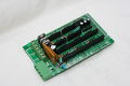
Bovenkant van de RAMPS 1.3


Veiligheids Tip
Zodra je met elektriciteit aan de slag gaat - ook al is het maar twaalf volt - wees dan verstandig en gebruik je gezond verstand zodat branden worden voorkomen. Mocht dit toch niet werken, dan test je je werkplaats smoke detector op brandweerbaarheid. Heb je geen brand-detector? Heel handing om te hebben!.
Assemblage
Componenten Solderen
Shield Assemblage
Voor beginnende elektronici is het wellicht aan te raden om vanuit het midden naar de rand van het printplaatje te solderen.
Anderzins kun je onderstaande volgorde afwerken- Weerstanden zoals getoond rechts.
- Een kleine 100nF condensator, C4 (geel)
- LED - Positieve draad (lange draad) aan 'bovenkant' van de printplaat, lange (korte draad) aan de 'onderkant' van de printplaat.
- D2 1N4004 de diode net boven de reset knop. Zorg er voor dat de streep op de diode oplijnd met de streep van het diodesymbool op de printplaat.
- Er zijn acht 2x3 mannetje pin connectors die je op de printplaat kunt plaatsen. Ze zijn bedoeld voor de microstap instellingen voor de stappenmotoren en de eindstops. Instelling van de microstappen vind plaats met behulp van jumpertjes. Om de pin connectors te solderen op de printplaat is het het makkelijkst om een (speel)kaart te nemen, ze op de pinheaders te plaatsen, en dan het geheel (printplaat + pinheaders) om te draaien. Zorg er voor dat de korte kant van de pin connectors in de printplaat steken. Zorg er ook voor dat je de pin-connectors voor de eindstops niet een gaatje naar rechts hebt verschoven. Dan vallen ze namelijk in de gaatjes voor de I2C aansluitingen.
- Soldeer 6x1 mannetje pin connectors in de T0, T1, & T2 gaatjes voor de thermistor aansluiting. Soldeer eerst een van de pinnetjes vast, plaats de overige pinnetjes recht ten opzichte van de printplaat en soldeer ze vast.
- Soldeer 1x4 mannetje pin connectors voor de motor connectors. You need to put these in the 4 pads next to X,Y,Z,E0, & E1. If your bot uses 2 motors on Z axis put 2 sets on Z (else you can just use 1 on Z).
- Twee 1x24 connector headers op hun plaats voor de the X,Y, and Z stappenmotor driver connectors.
- (4) 1x8 connector headers op hun plaats voor de E0 & E1 stappenmotor driver aansluitingen.
- Soldeer de grote condensators, C4, de 100nF condensator, C5,C8 10uF condensation zoals rechts boven.
- Ze moeten in de kaart worden gestoken met de juiste orientate. + aan bovenkant voor C4 en C5 of links voor C8.
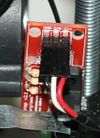
- Mosfets, Q1,Q2,Q3, de drie N-kanaals mosfet, STP55NF06L (deze kunnen mooi recht worden gemonteerd door een van de pinnen vast te solderen, de mosfet rechtop te plaatsen en vervolgens de andere pinnen vast te solderen.)
- Ze moeten juist worden gemonteerd zoals op de foto.
- De grote gele MF-R500 zekering (F1) en de grotere gele MF-R1100 zekering (F2).
- Power connector, X1, de 4 pinnige fixed/pluggable terminal block.
- De 6 pins Schroef terminal block
- Pass-through connectors die de shield verbinden met het Arduino bored (geplaatst langs de randen van het bordje). This includes the (1) 2 x 18 Pin Stackable Female Header, the (5) 1 x 8 Pin Stackable Female Header and the (1) 1 x 6 Pin Stackable Female Header.
- More recent kits include 2x18, 1x22, and 1x24 pin headers for connection to the Arduino MEGA. Cut the 1x24 headers into (1) 1x6 + (5) 1x8 lengths. If you insert these into the Arduino MEGA to hold them straight while soldering, take care not to heat for too long risking melting the Arduino's connector.
- You can omit D1, the 1N4004 diode. The diode can be omitted, it may be needed in the future for printing from SD or USB. This will power the Arduino from the shields 12V input. Diodes must be oriented correctly.
If you are using higher than 12V to power the shield you should omit the diode to prevent damage to the Arduino and stepper drivers.Warning: The high side of the stepper boards are designed to accept up to 35V, but if you do this the heater and other high side outputs will be at that voltage also. You may need to adjust the heater resistance, etc.
- Reset switch, S1, push button switch
- Thoroughly check for shorts (This is crucially crucial for DIY etched boards.)
- Check for continuity between each and every pin to the pins next to them and GND, 12V, 5V (VCC).
- Set your meter to beep for continuity, hold a probe on GND and check all soldered pins. If it beeps check if it is supposed to be GND and contine. Repeat for 12V and 5V.
Stappenmotor Driver Bordjes
- Jumpers moeten worden geinstalleerd onder elke stappenmotor drijver:
| 1 | 2 | 3 | |
| nee | nee | nee | volledige stap |
| ja | nee | nee | halve stap |
| nee | ja | nee | 1/4 stap |
| ja | ja | nee | 1/8 stap |
| ja | ja | ja | 1/16 stap |
Op dit moment is de voorinstelling 1/16 micro stappen (alle jumpers zijn geïnstalleerd onder de drivers)
- Cut the pin headers to 8 pins long so that they fit each side of the stepper driver.
- Insert the pin headers into the sockets on RAMPS
- Fit the stepper drivers onto the pin headers and solder. Only heat each pin for a few seconds at time to avoid damage to the socket.
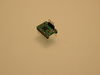
- Glue the heatsink (if used) to the top of the A4983 chip using the provided pad of double-sided adhesive.

Optische Eindstops
- Cut the 26awg 3 conductor cable into 3 length.
- Note: you may want until you've built your machine to cut the cables to the perfect length.
- WARNING In order to keep the PCB at a printable resolution two wires have been flipped from the traditional opto endstop boards. The signal pin has been moved to the outside of the connector.
- Hooking these up incorrectly can damage the components.
- crimp and solder a female connector to the ends of each wire. (solder not necessary with proper crimp tools)
- use the 2.54mm 1x3 housing.
- Connect at least the minimum endstops.
- Cut the 26awg 3 conductor cable into 3 length.


| RAMPS Eind | |
| SIG (S) | Wit |
| GND (-) | Zwart |
| VCC (+) | Rood |
| Endstop End | |
| VCC (+) | Roord |
| SIG (S) | Wit |
| GND (-) | Zwart |
Mechanical Endstops
The recommended firmwares provide a configuration to use mechanical endstops with just these two wires.
Connect GND on RAMPS to C on the switch. Connect S on RAMPS to NC on the switch.
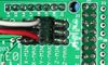
Put the connectors on the motor wires
- solder a female connector to the ends of each wire.
- use the 2.54mm 1x3 housing.
- Shown is the type used for servos in RC projects. See Stepper Motors for info on motors.
Thermistor Wires
Use a 2 pin 0.1" connector to terminate the thermistor wires.
- Connect the cable so the 2 wires go to T0
- Connect the 2 heater wires to D10 (E0H on older boards) and the + connection above it.
- If changing to an unverified firmware it is best to verify heater circuit function with a meter before connecting heater to prevent damage to the extruder.
Final Setup
Bedrading
Het is relatief simpel om de RAMPS te bedraden. Verbind de extruder verwarming draad met D10, de thermistor met de twee T0 pinnen op midden rechts rechts, en verbind de stappenmotoren en eindstops. Van links naar rechts verbind alle draden van de stappenmotoren met de kleuren rood, blow, groen, en zwart of rood, groen, geel, blauw op de pinnen naast de Pololus. Wanneer je de draden verbind met de eindstops (als je drie eindstops hebt, plug ze in de MIN (-) slots) zorg dan dat ze overeenstemmen met de labels.

Pre-Flight Check
If you think you may have mistakes you can install only one stepper driver during initial testing and risk only one stepper driver.
The trimpot on the stepper drivers controls the current limit. Turn it all the way down (counter clock wise) and back up 25%. Be careful to not force the trimpot, it is delicate. You will need to fine tune the current limit later. Note that it is allways giving the motors that much power, even when not moving, so if your stepper motor drivers are getting hot, you may want to turn it down slightly.
Connect the minimum endstops for X,Y, and Z
Connect Motors (Do not disconnect or connect motors while powered; if the connection is loose, this will cause the motors to spazz and possibly kill your stepper driver.)
Install firmware (More info below). Firmware flashing can be done without 12V power supply connected.
Waarschuwingen
Het omdraaien van +/- of op een andere manier verkeerd verbinden van de voeding kan je electronica kapot maken en wellicht brand veroorzaken.
Het verkeerd verbinden van de stappenmotor drivers zal je elektronica kapot maken en wellicht brand veroorzaken.
Zorg er ALTIJD voor dat de voeding en USB zijn losgekoppeld wanner je stappenmotor drivers verwijderd of bijstelt. Zorg er ook voor dat je de drivers met de juiste oriëntatie en goed in hun contactvoeten plaatst.
De eindstop pinnen hebben de namen Signal - GND - VCC, inplaats van de VCC - Sig - GND zoals de rest van de RepRap bordjes. Bedraad ze dus op de juiste manier. Dit is gedaan om er dikkere printbanen op het bord te kunnen printen.
Connecting Power

Connect your 12V power supply to the RAMPS shield.Reversing +/- or otherwise incorrectly connecting power can destroy your electronics and cause fire hazard
The bottom pair of connectors marked 5A power the stepper drivers and Extruder heater/fan (D9,D10). The power supplied to these should be rated a minimum of 5A.
The pair of connectors above marked 11A power a Heated Bed, or other output (D11). The power supplied here should be rated a minimum 11A. (If both power rails are connected to the same supply it should have a minimum rating of 16A)
The barrel connector on the Arduino MEGA is not used for our application.
The power connector plug may not be obviously labeled, looking at the power connection the positive is on the left and the negative is on the right of the plug.
Power Supply
RAMPS 1.3 uses RAMPS is quite happy with the 12 V line from PCPowerSupply. Or you can hack up a 12V laptop power supply, or other 12 V "wall wart" power supply. Be sure that the power can output 5A or greater. Additional 11A may be needed for heated bed support.
See Connecting power above.
Maximum Ingang Voltage
Voeding zonder diode
De 1N4004 diode verbind de RAMPS ingang voltage met de MEGA. Als de printplaat niet de diode niet bevat , kun je veilig spanningen tot 35V gebruiken. (De pololus kunnen 35V maximaal aan.)
Voeding met diode
Als de printplaat een 1N4004 diode heeft geplaatst dan is het bord belastbaar met maximaal 12 V. Originele Arduino Megas zijn belastbaar tot 12 Volt. Hoewel de Arduino Mega 2560 20V kan verdragen, wordt dat niet aangeraden.
Laatste Controle

Merk op dat tesla & tonic firmware d9 gebruiken en sprinter en johnny/tonok d10 gebruiken voor de extruder hete print kop.
Firmware and Pin Assignments
You will need the Arduino software at http://www.arduino.cc/en/Main/Software to upload the firmware to Arduino Mega.
Working preconfigured firmwares are available at:
Preferred: (Need pins set in firmware as below)
https://github.com/tesla893/Tonokip-Firmware - Tesla893's Tonokip-Firmware fork, works w/ RepSnapper and Skeinforge - Added Features over original Tonokip but not as up to date as Klimentkip
https://github.com/kliment/Klimentkip - Kliment's Tonokip-Firmware Fork with Acceleration, PID, SD support, and other goodies - Updated frequently, with many active developers/hackers/users.
Others (Need pins set in Firmware as below):
https://github.com/johnnyr/Tonokip-Firmware works excellently with RepSnapper and Skeinforge - Not as current
https://github.com/ramps/FiveD_for_RAMPS_GCode_Interpreter for use with Host Software or ReplicatorG or RepSnapper
- mechanical endstops (now the default ultimachine.com option) require #define OPTO_PULLUPS_INTERNAL 1 to be added to configuration.h
There are predefined pins for FiveD_on_Arduino in git master, but support is experimental. Programming works following the instructions in the wikipage.
Here are the pin definitions for this board.
// For RAMPS 1.3
#define X_STEP_PIN         54
#define X_DIR_PIN          55
#define X_ENABLE_PIN       38
#define X_MIN_PIN           3
#define X_MAX_PIN           2

#define Y_STEP_PIN         60
#define Y_DIR_PIN          61
#define Y_ENABLE_PIN       56
#define Y_MIN_PIN          14
#define Y_MAX_PIN          15

#define Z_STEP_PIN         46
#define Z_DIR_PIN          48
#define Z_ENABLE_PIN       62
#define Z_MIN_PIN          18
#define Z_MAX_PIN          19

#define E_STEP_PIN         26
#define E_DIR_PIN          28
#define E_ENABLE_PIN       24

#define SDPOWER            -1
#define SDSS               53
#define LED_PIN            13

#define FAN_PIN            9

#define PS_ON_PIN          12
#define KILL_PIN           -1

#define HEATER_0_PIN       10
#define HEATER_1_PIN       8
#define TEMP_0_PIN          13   // ANALOG NUMBERING
#define TEMP_1_PIN          14   // ANALOG NUMBERING
Source
| FILE ID# | TYPE | DESCRIPTION | DOWNLOAD |
|---|---|---|---|
| File:ArduinoMegaPololuShield.zip | Eagle Files | These are the files you need to make the board.(Use the File: link to the left to access older versions of the file.) | media:ArduinoMegaPololuShield.zip |
| File:RepRapjr.lbr | Eagle Libraries | The components used in this board are here. see Eagle_Library | media:RepRapjr.lbr |
Bill of Materials
| ID | Description | Quantity | Part Number | Reichelt Order Number |
|---|---|---|---|---|
| U1 | Arduino Mega | 1 | 2560 or 1280 | |
| U2,U3,U4,U5 | Pololu A4983 carrier | 4 | A fifth one can be used for a 2nd extruder or extra axis | |
| C4 | 100nF capacitor (> highest planned voltage) | 1 | X7R-2,5 100N (verified) | |
| C1,C5,C8 | 10uF capacitor (>5V) | 3 | RAD 10/35 (verified) | |
| C6 | 100uF capacitor (> highest planned voltage) | 1 | RAD 100/25 (verified) | |
| R1,R7,R11 | 4.7K resistor (250mW 1%) | 3 | METALL 4.70K | |
| R2,R3,R4,R5,R6,R8,R9,R10 | 100K resistor (250mW) | 8 | 1/4W 100K | |
| R12 | 1K resistor (250mW) | 1 | 1/4W 1K | |
| Q1,Q2,Q3 | N-channel Mosfet | 3 | STP55NF06L | ZXM 64N035 L3 |
| D1,D2 | Diode | 2 | 1N4004 | 1N 4004 |
| F1 | PTC resettable fuse (30V, Hold5A, Trip10A) | 1 | MF-R500 | PFRA 500 |
| F2 | PTC resettable fuse (Hold11A) | 1 | MF-R1100 | |
| J2 | 5.08 Eurostyle screw terminal (Min 11A per position more is better) | 1 | 282837-6 | AKL 101-06 |
| LED1 | 3mm Green LED | 1 | LED 3MM ST GN | |
| S1 | Push button switch | 1 | FSMRACD | TASTER 3305B |
| X1 | Power jack (Plug and fixed receptacle)(Min 11A per position more is better) | 1 | MSTBA 2,5 and MSTBT 2,5 (5.04mm spacing 4 connector) | |
| 2 x 3 pin header | 8 | |||
| 4 pin header | 5 | SL 1X36G 2,54 (3 of these) | ||
| 6 pin header | ||||
| 2 x 18 Pin Stackable Female Header (non stackables can be used with plated through holes) | 1 | MALE: SL 2X25G 2,54 (2 of them, shortened with a saw or pliers) | ||
| 8 Pin Stackable Female Header (non stackables can be used with plated through holes) | 5 | |||
| 6 Pin Stackable Female Header (non stackables can be used with plated through holes) | 1 | |||
| 24 Pin Female Header * Note * | 2 | Required to carry enough current for motors | ||
| 8 Pin Female Header * Note * | 4 | Required to carry enough current for motors | ||
| 0.1" Jumpers | 15 | |||
| Circuit Board | 1 | v1.3 |
Note * You can use Female Headers which are not the exact size, but they are hard to break/cut so in this case buy some extra! (one wasted header per cut)
A (OUT OF DATE - shopping list for v1.2, needs updated to above list for 1.3) shopping cart for the german distributor reichelt has been assembled (by lImbus).
An untested BoM for RAMPS 1.3 is available at Mouser (USA).